Panasonic Toughbook CF-29 Motherboard Replacement
ID: 2476
Description: This guide will tell you how to gain access to...
Steps:
- Locate the bay door for the battery on the left side of the laptop.
- Slide the latch to the right and then down to unlock it.
- Pull out the battery.
- Locate the door for the hard drive on the right side of the laptop
- Push and slide the latch up to open the hard drive door.
- Pull out the hard drive.
- Flip the device upside down with the handle facing away from you.
- Open the optical drive bay by sliding its latch to the right.
- Locate optical drive release mechanism on the bottom of the laptop.
- Slide the latch cover to the right.
- Push the exposed switch to the left to eject the optical drive.
- Begin by turning the laptop upside down with the handle towards you.
- Use a Phillips size 0 screwdriver to remove the 4 screws holding down the ram cover.
- Remove the panel and set it aside.
- Use a Phillips size 0 screwdriver to remove these 8 small screws.
- Use a Phillips size 1 screwdriver to remove the remaining 8 screws.
- Use a plastic opening tool to release, but NOT remove, the back cover because it is sealed with adhesive.
- Be careful when lifting the cover as you may damage some connections.
- Slowly lift the cover so that you can disconnect the red and white wires connecting the speaker to the sound card.
- Now the back cover should be off and you can access the inside of the casing.
- Remove the black and white wires attached to the wireless card by simply pulling up.
- Peel back the black cover to expose the clips holding in the wireless card.
- Using a pair of plastic opening tools, push the two metal tabs away from the card.
- The wireless card should now easily disengage from the motherboard.
- Pull the card horizontally away from you to remove it from its housing.
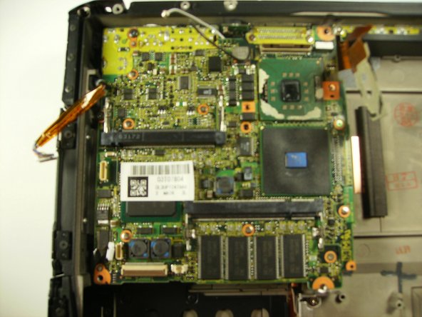
- Unplug 3 cables
- Lift up on brown tab to release cable
- Pull cable up and out
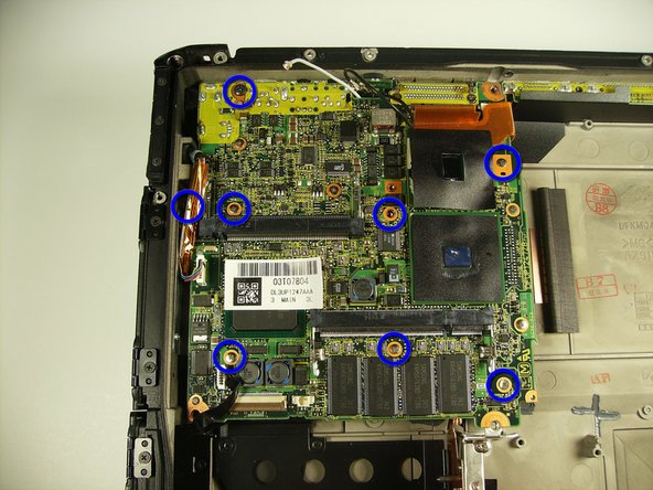
- Remove 2 long screws indicated with red circles
- Remove the remaining screws indicated in blue
- On the back of the unit, unscrew the three screws surrounding the serial port.
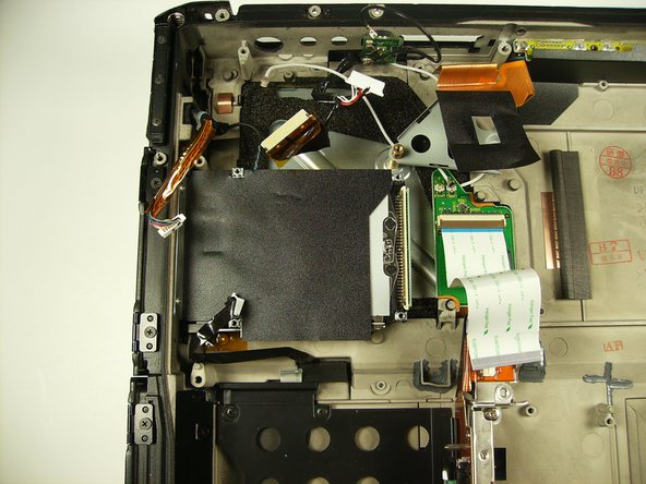
- Lift the motherboard as shown, pull towards you and then up.
- Do not yet try to fully remove the motherboard or you may destroy the connections
- Detach the white ribbon cable, the white cluster connector, and the ribbon cable right next to the cluster
- Remove the board.