Sony Vaio VGN-S260 Fan Replacement
ID: 2366
Description: How to disassemble the fan of a Sony Vaio...
Steps:
- Flip the laptop over so the Vaio logo is facing down.
- Locate the battery at the top and Find the release and unlock slides on the battery.
- Slide the unlock tab to the unlock position.
- Slide the release tab in the direction of the arrow, i.e. towards the unlock tab.
- With the tabs still in the unlock position, slide the battery away from the main case.
- Flip the computer over so the Vaio logo is facedown.
- Unscrew the 2 screws next to the battery.
- Flip the computer over again so the Vaio logo is face up.
- Open the lid.
- Press down on the outer gray shell around the keyboard.
- Use the spudger to gently lift keyboard.
- Do not pull up the keyboard too far as it is attached to a ribbon underneath.
- Lift up lever underneath the ribbon to detach the keyboard.
- Remove memory/wireless compartment cover.
- Flip so the Vaio Logo is face down.
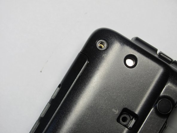
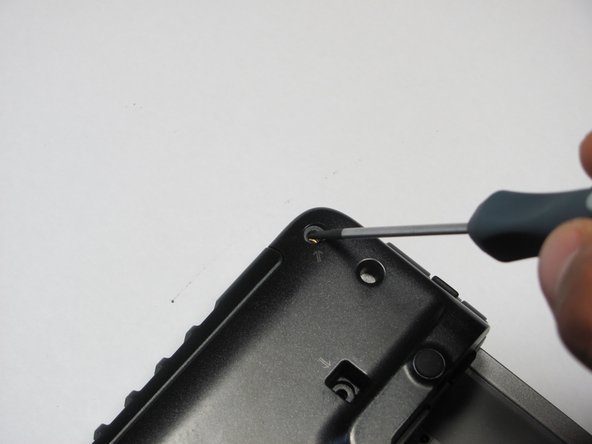
- Locate and remove a total of 8 screws on the bottom.
- Find and remove 5 screws (they all have arrows next to them) from cover.
- Flip the laptop over so the Vaio logo is face up.
- Use the spudger to pop up the upper casing.
- Do not lift too much as the upper casing is attached to wires underneath.
- Remove the wires that are attaching the upper casing to the motherboard.
- Remove the upper casing.
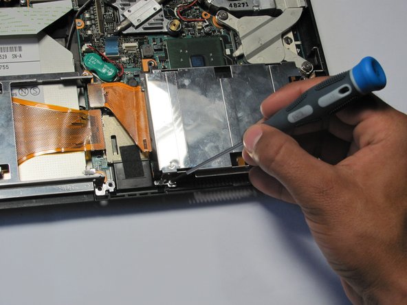
- Remove the screw holding the optical drive casing to the logic board.
- Locate ribbon connecting optical drive case to logic board.
- Pop off the ribbon.
- Remove the metal PC-Card cage.
- Remove the four screws holding the optical drive to the logic board.
- Locate brown locking tab above optical drive.
- Lift up on brown locking tab until ribbon is loose.
- Gently slide out and remove the optical drive from the computer.
- Remove the blue ribbon from the Ethernet Circuit Board.
- Remove the screws near the Ethernet Port circuit board.
- Remove the screws for the second ethernet circuit board.
- Remove the ethernet ports.
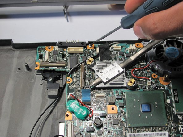
- Remove the screws holding the hard drive casing in place.
- Find orange ribbon that is connected to the hard drive.
- Find the holder of the ribbon and pop the ribbon off from it.
- Remove the casing and the orange ribbon.
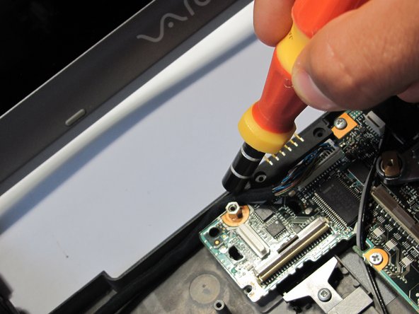
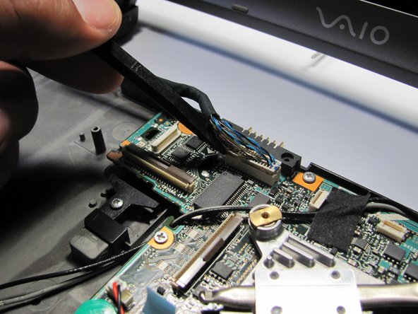
- Locate the yellow power adapter.
- Follow its wire to white logic board connector.
- Pull out the wire from white logic board connector.
- Locate the screws on the fan filter casing.
- Remove these screws.
- Remove the screw next to the yellow power adapter.
- Lift out power adapter and fan filter.
- Remove screws on the motherboard.
- Remove the nut using a 5mm nut driver.
- Using a magnetic screwdriver handle will also work as well.
- Remove the LCD display ribbon with a nylon spudger.
- This is difficult to remove.
- Gently lift the motherboard from the laptop.
- The motherboard will be attached to the network wireless chip, which is also attached to the base of the laptop.
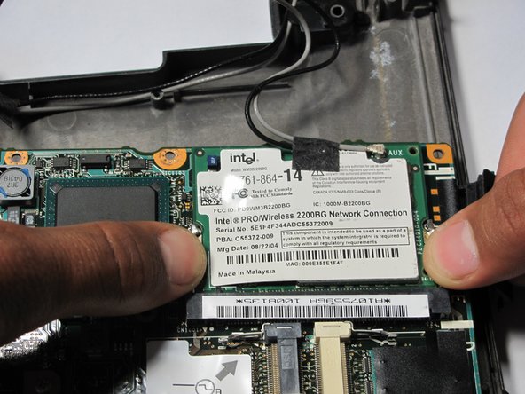
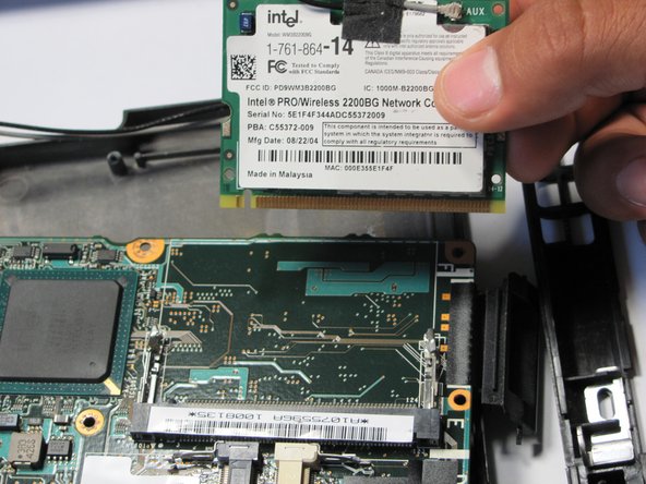
- Remove the chip by popping the tabs on the side.
- Slide out the network card.
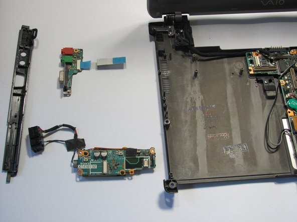
- You are now free to take the motherboard away from the base.
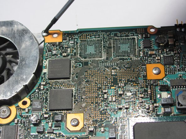
- Disconnect the fan wire from the logic board
- Turn the logic board over and Locate the screws connecting the fan to the logic board
- Remove these screws
- Gently remove the fan from the logic board