Sony Cyber-shot DSC-W150 LCD Screen Replacement
ID: 2539
Description: This guide will instruct you on how to replace...
Steps:
- The screws from the camera are extremely small, so it is a good idea to have a small container to hold all the screws as you remove them.
- Take your screwdriver and remove the four silver bottom screws of the camera.
- The picture shows the lens facing away from you and the LCD facing you.
- On the right side of the camera, remove the two silver screws using the screwdriver.
- The picture shows the lens facing away from you and the LCD screen facing you.
- On the left side of the camera, remove the two silver screws using the screwdriver.
- The picture shows the lens facing away from you and the LCD screen facing you.
- Gently detach the back cover by holding onto both sides of the camera and pulling them apart.
- After detaching the back cover, carefully pull it off.
- The back cover should now be separated from the camera.
- Keep track of the small screws that you remove.
- Opening, removing, and/or replacing the front casing may void your manufacturer's warranty.
- Remove the two screws at the top of the camera casing.
- After removing the screws, gently pop open the plastic piece, as shown by firmly pulling it with your fingers.
- After popping open the plastic piece, there is a screw that needs to be removed.
- Remove the screw connecting the front casing to the electrical components.
- On the casing on the opposite side of the camera, gently loosen and remove the casing by firmly pulling with your fingers.
- Be cautious not to break the fragile pieces or scratch the LCD screen.
- Remove the two screws connecting the front casing to the electrical components using a screwdriver.
- Gently loosen the front casing by gently using your fingers to pull it apart.
- Be cautious not to scratch any of the exposed electrical components.
- Fully remove the front casing from the camera and set it aside.
- The last screw is in the bottom left corner of the camera's right side.
- Using a screwdriver, remove the last screw holding the LCD/control panel to the rest of the camera on the right-hand side.
- It is crucial for reassembly to track which screws were removed from which holes.
- At this point, all screws on the left and right sides of the camera should be removed.
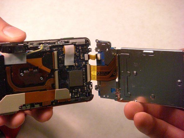
- Paying careful attention to the right side's electrical wiring, gently pull the left side of the LCD plate away from the rest of the camera.
- DO NOT detach the electrical wiring connecting the right side of the LCD and the camera.
- This picture is used to identify the action required to release the electrical ribbons, but not the proper location for this step.
- This step applies to the larger electrical ribbon connecting the LCD screen and circuit board.
- Using a spudger, wedge the flat-tipped end between the black bar and the circuit board.
- Carefully lift the black bar into the vertical position.
- After raising the black bar, the electrical ribbon should be free from its port.
- Use tweezers to carefully pull the larger electrical ribbon from its circuit board port.
- The smaller electrical ribbon, to the left of the larger ribbon, does not have a black bar securing it in place.
- Use tweezers to pull the smaller electrical ribbon carefully from its circuit board port.
- Desolder the small electrical ribbon that connects the control panel to the LCD screen.
- Now the LCD/control panel is completely removed from the part and ready to be replaced.