Canon Powershot SD550 Flash Bulb Assembly Replacement
ID: 5310
Description: The flash bulb is essential for to take dimly...
Steps:
- Remove the battery and SD card from the camera.
- Remove the three 3.8 mm screws from the underside of the camera.
- Each of the screws is slightly different, so it is important that you note the original location of each screw.
- Remove the 3.2 mm screw from the right side of the camera.
- Remove the 2.2 mm screw from the right side of the camera.
- One of these screws is hidden under the USB port cover.
- Lift the side panel off.
- Remove the 1.8 mm screw from underneath the side panel.
- Remove the two 2.2 mm screws from the left side of the camera.
- Lift the plate from the camera.
- Gently lift the rear of the case to remove it from the camera.
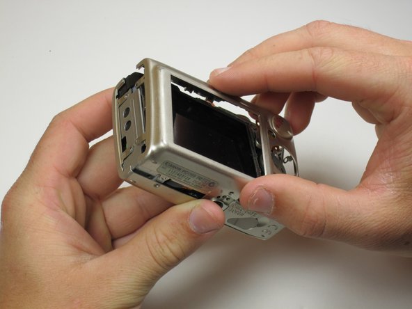
- Remove the front of the camera body.
- Be sure to keep track of the rubber ring.
- Peel the navigation buttons from the button panel and set them aside.
- To free the LCD display, remove the 2.9 mm screw in the top left corner.
- Rotate the screen clockwise until it lifts away from the camera.
- There are two ribbon cables attached to the rear of the screen. Do not try to pull the screen off at this point.
- To unplug the ribbon cables, pull them straight out of their plugs. Do this gently to avoid damaging the connections.
- After disconnecting both cables, pull the screen away from the camera to remove it.
- Once the image sensor is removed, turn the camera over and find the screw in the bottom right corner.
- Remove this .01 inch screw to free the ribbon cables.
- One by one, detach the three ribbon cables from their ports.
- Pay special attention when removing this connector. It does not pull out like the rest of them. Instead, you must use a spudger to lift the connector vertically out of its slot.
- Flip the camera over again so that the rear is showing and remove the two .065 inch screws holding the flash unit in place. They should be on the left side.
- Now you should be able to remove the flash unit from the camera.
- When removing the flash, be careful when handling the capacitor. It may contain a powerful charge. Discharge may result in damage and personal injury.
- You have now successfully removed the flash unit.