Canon Powershot SD550 Motherboard Replacement
ID: 5302
Description: This guide provides the steps to follow to...
Steps:
- Remove the battery and SD card from the camera.
- Remove the three 3.8 mm screws from the underside of the camera.
- Each of the screws is slightly different, so it is important that you note the original location of each screw.
- Remove the 3.2 mm screw from the right side of the camera.
- Remove the 2.2 mm screw from the right side of the camera.
- One of these screws is hidden under the USB port cover.
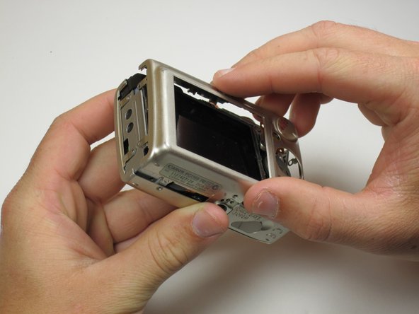
- Lift the side panel off.
- Remove the 1.8 mm screw from underneath the side panel.
- Remove the two 2.2 mm screws from the left side of the camera.
- Lift the plate from the camera.
- Gently lift the rear of the case to remove it from the camera.
- Remove the front of the camera body.
- Be sure to keep track of the rubber ring.
- Peel the navigation buttons from the button panel and set them aside.
- To free the LCD display, remove the 2.9 mm screw in the top left corner.
- Rotate the screen clockwise until it lifts away from the camera.
- There are two ribbon cables attached to the rear of the screen. Do not try to pull the screen off at this point.
- To unplug the ribbon cables, pull them straight out of their plugs. Do this gently to avoid damaging the connections.
- After disconnecting both cables, pull the screen away from the camera to remove it.
- Remove the two 3.4 mm screws still holding the button contact panel onto the camera.
- Using the spudger, disconnect the ribbon cable attaching the button contact panel to the motherboard.
- Gently pull the button contact panel away from the motherboard.
- Underneath the button contact panel, you will find a large connector.
- Using the spudger as leverage, unplug the connector, and pull it away from the motherboard.
- The last ribbon is held in place by the blue flap. Insert the spudger under the blue flap.
- Using the spudger as leverage, flip the blue flap up, which will unlock the ribbon.
- Place the spudger into the hole in the ribbon, and pull the ribbon away from the connector.
- Remove the motherboard by pulling it out with either tweezers or the spudger.