iMac Intel 24" EMC 2111 Left Speaker Replacement
ID: 5204
Description: Use this guide to replace a blown left speaker.
Steps:
- Loosen the two Phillips screws securing the access door to your iMac.
- Both screws remain captive within the access door.
- Remove the access door.
- Remove the following screws along the lower edge of your iMac:
- Three 6 mm T8 Torx screws
- One 8 mm T8 Torx screw
- Lay your iMac stand-side down on a flat surface.
- To lift the front bezel off the iMac, simultaneously:
- Use your thumbs to press in the RAM arms and hold the iMac down.
- Use your index fingers to pull the small bridge of material on the front bezel toward yourself.
- Pull the front bezel up with your index fingers.
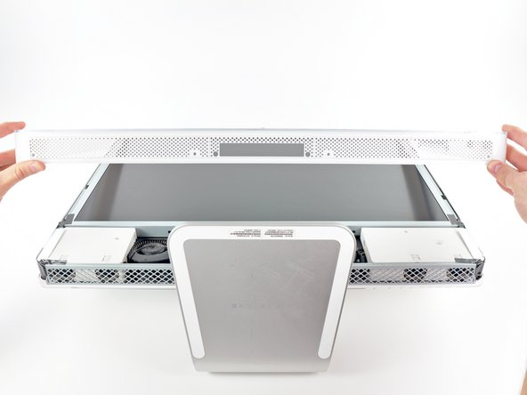
- Once the small bridge of material has cleared the RAM arms, lift the front bezel by its lower edge just enough to clear the bottom edge of the rear case.
- Lift the front bezel off the rear case and rotate it away from the bottom edge of the iMac, minding the camera and microphone cables still attached to its upper edge.
- The third picture shows the top front bezel brackets and their slots cut into the top edge of the iMac's rear case.
- Do not completely remove the front bezel, as it is still attached by the camera/microphone cables.
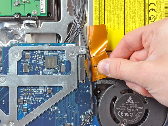
- If necessary, remove the strip of tape covering the microphone cable connector.
- The microphone connector is located near the inside of top edge of your iMac.
- Disconnect the microphone cable.
- Disconnect the camera cable by pulling its connector away from the socket on the camera board.
- The camera cable connector and socket are delicate and easily bent. Remove with caution.
- Peel the two highlighted EMI shield tabs off the frame of the LCD.
- Remove the two T6 Torx screws securing the display data cable to the logic board.
- Pull the black plastic tab attached to the display data cable connector to disconnect it from the logic board.
- Use your fingertips to pull both sides of the wide inverter cable connector out of its socket on the logic board.
- De-route the inverter cable from its location next to the CPU fan.
- Before attempting this step, we recommend laying your iMac stand-side down on a table to avoid the display falling down.
- Remove the eight T8 Torx screws securing the display assembly to the rear case.
- It is helpful to use a thin magnetized screwdriver to remove these screws.
- Remove the display assembly from the iMac.
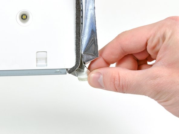
- Peel back the piece of EMI tape connecting the bottom edge of the right speaker to the metal frame of the iMac.
- Peel the tape away from the lower corner of the right speaker.
- De-route the right-hand speaker's cable from between the logic board and the optical drive fan.
- Disconnect the cable from the logic board.
- Remove the 26 mm T10 Torx screw securing the right speaker to the iMac.
- Pull the right speaker away from the logic board and remove it from the iMac.
- Use the flat end of a spudger to pry both antenna connectors off their sockets on the AirPort card.
- The black antenna attaches closest to the bottom edge of the iMac.
- Use both fingertips to disconnect the camera and microphone cable from its socket on the logic board.
- Pull the connector perpendicular to the face of the logic board.
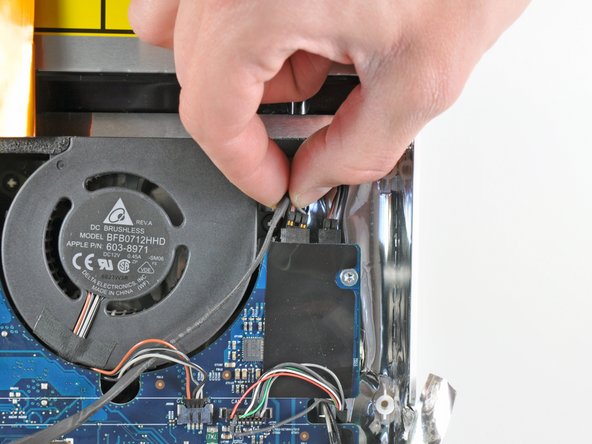
- Pull the optical drive fan connector toward the top edge of the iMac to disconnect it from the logic board.
- Pull the left speaker connector toward the top edge of the iMac to disconnect it from the logic board.
- Pull the optical drive thermal sensor connector toward the right side of the iMac to disconnect it from its socket.
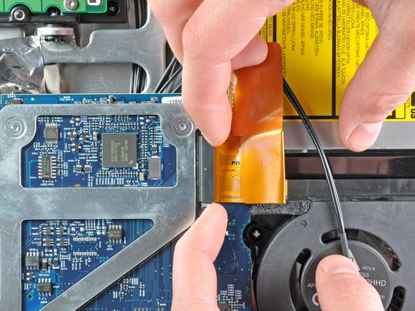
- If necessary, remove the strip of tape covering the optical drive connector.
- Gently pull the cable retainer on the optical drive cable ZIF socket toward the right side of the iMac.
- The retainer should move about 1 mm and stop. Do not attempt to remove the retainer.
- Pull the optical drive ribbon cable out of its socket, being careful not to rip it in the process.
- Disconnect the hard drive thermal sensor and hard drive fan cables from the logic board by pulling their connectors toward the top edge of the iMac.
- Pull the CPU fan connector toward the left edge of the iMac to disconnect it from the logic board.
- Disconnect the power button cable from the logic board.
- Pull its connector perpendicular to the face of the logic board.
- Use the flat end of a spudger to pry the single Bluetooth antenna off its socket on the Bluetooth board.
- Pull the ambient temperature sensor cable perpendicular to the face of the logic board to disconnect it from its socket.
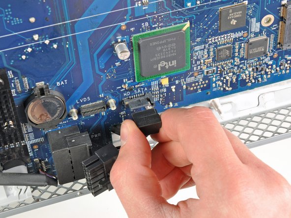
- Disconnect the DC-In cable from the logic board by pulling its cable toward the right side of the iMac while depressing its locking mechanism.
- It is helpful to use a spudger and pry from alternating sides of the connector to help "walk" it out of its socket.
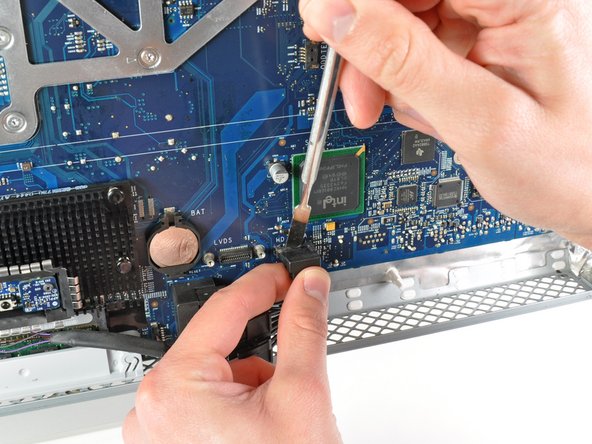
- Pull the hard drive SATA data cable perpendicular to the face of the logic board to disconnect it from its socket.
- To avoid damaging the socket on the logic board, we recommend using a metal spudger to help separate the SATA data cable and its socket.
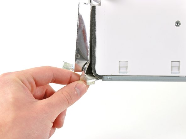
- Peel the foam tape off the top edge of the heat sink framework.
- Remove the following ten screws:
- Three 6.6 mm T10 Torx fine thread screws
- Three 7 mm T10 Torx coarse thread screws
- Two 9.3 mm T10 Torx coarse thread screws
- Two 5.3 mm T10 Torx coarse thread screws
- Pull the right edge of the logic board slightly away from the rear case to dislodge the rear I/O ports from their bezel.
- Tilt the top edge of the board away from the rear case and lift the logic board assembly out of the rear case, minding any cables that may get caught.
- When reinstalling the logic board, it is helpful to use tape to temporarily tuck the cables out of the way until the board is properly seated in the rear case.
- During reassembly of the logic board, pay attention to the position of the I/O connectors. When the board is back in the case, insert a USB or Thunderbolt cable into one of the connectors to align it perfectly.
- Lift the optical drive fan off the plastic posts protruding from the rear case.
- During reinstallation, be sure to re-route the cable the way you found it.
- Remove the pieces of tape securing the left speaker cable to the rear case.
- We have found it easier to just cut the tape near the cable for removal. During reinstallation, simply apply a new piece of tape over the cable.
- De-route the left speaker cable from beneath the framework near the center of the iMac.
- Peel back the strip of EMI tape near the bottom edge of the left speaker.
- Pull the EMI tape away from the bottom corner of the left speaker.
- Remove the 38 mm T10 Torx screw securing the left speaker to the rear case.
- Pull the left speaker out of the iMac, minding any cables that may get caught.
- If your replacement left speaker does not have an ambient temperature sensor attached, use the edge of a spudger to peel it off the existing speaker and transfer it to your new speaker.