Disassembling Creative ZEN Screen and Battery
ID: 5171
Description: The ZEN's case is held together with 8 snaps....
Steps:
- Here's the beast we'll be dissecting. It's a rare 32GB version that's been having some white-screen issues (if you haven't heard, that's a common issue).
- Now is the time to consider whether you want to risk destroying your ZEN. The risk is small if you do it right, but remember this: you're choosing to open it. If you break it, it's your fault. Don't be dumb, don't force things. Use your brain.
- Find the left side of the ZEN. You can see in the picture that I learned by trial & error how to open my ZEN. If you do it right, you won't leave those gouge marks on the case.
- The red rectangles indicate where the tabs are inside the case. They are 0.5" in from the outer edge.
- Insert one thin screwdriver in the seam of the case right over the tab (red rectangles, remember?). Pry upward (gently!), forcing the lower half of the shell to flex outward. See pics 2 & 3.
- Once you have the first screwdriver worked in (don't push it in very far, there's a battery close to there), use the other screwdriver to work open the second tab. You'll want both screwdrivers in the ZEN at the same time, like in picture 1. You'll notice that the bottom shell has started to separate.
- Remove one of the drivers, trying not to let the case snap back together. Move it to the side (bottom or top) that is closer to the side that still has its driver stuck in. Locate the tab closest to the corner (red rectangle again), 0.5" in again. Free this tab, and hold the corner so that it stays open like in pic. 2.
- Release the other two tabs (marked in orange) in the same manner. They are 0.5" and 1.3" from the usb-port side. DO NOT TRY TO SEPARATE THE USB-PORT SIDE. There are different tabs holding it in, so we need to release the three other sides first.
- In the 3rd pic, you can see one of the actual tabs inside (far left rectangle). It's 0.5" in from the left side, and the others are 1.9" and 0.5" from the usb-port side. Release all these tabs (8 tabs in total).
- Open the case by lifting the non usb-port side slightly, then sliding the bottom shell towards the usb-port (see pics 1 & 2).
- In pic 3, we can see the horizontal pins (red circles) that hold the usb-port side of the case on. Those are why we have to open the case on 3 sides and slide it off.
- The blue square indicates the two wires that connect the button board to the main board. The yellow square indicates the battery wires, which are hidden under the RF shield.
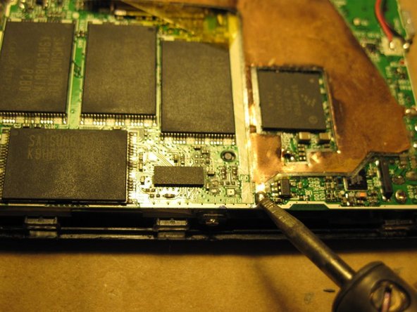
- Ideally we would disconnect the battery first. Unfortunately, the battery wires are soldered to the board underneath the RF shield. The first step is to remove the shield. It is soldered onto the main board in 4 places, circled in red.
- Using a low-heat, fine-tip soldering iron, carefully heat up the pads and lift the shield off the board. Be very careful not to splatter or spread any solder on the board itself.
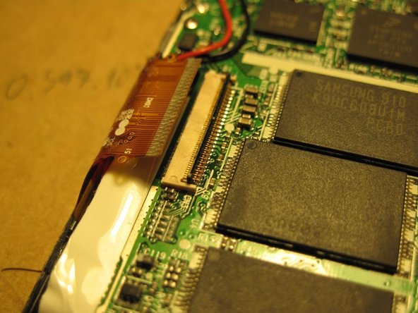
- The shield wraps around the LCD connector (upper left), but is only tucked in. It may be carefully pulled out, then placed aside.
- Now we'll pop open the LCD connector. The black rectangle on the OPPOSITE side of the ribbon cable flips up, rotating in the middle of the connector. Use your fingernail to gently flip it open, then pull the connector out.
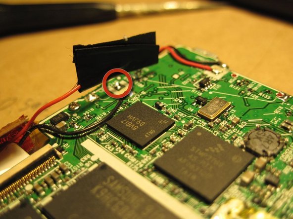
- The next thing to do is to disconnect the battery. Using your soldering iron, heat up the positive pad (circled in red in pic 3, surrounded by a white square on the actual PCB). Pull the wire away from the board and wrap it in electrical tape to prevent shorts. Be careful to only touch one pad at a time with the iron, as you may create a short if you touch multiple pads.
- Desolder both battery wires and both button wires (red rectangles). Gently bend them away from the board, being careful not to pull on them.
- Unscrew the 4 screws holding the main board down (blue circles). Slide the board to the right slightly, then lift it out. Place the screws in a pile designated "A". There are two different kinds of screws, as seen later.
- There are four more "A" screws on the sides of the device, circled in green. Remove them and put them in the "A" pile.
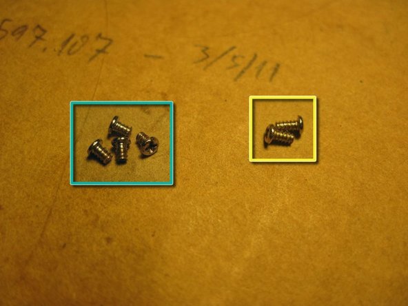
- The two screws circled in yellow are type "B" screws. Remove them and put them in a separate pile.
- The 3rd pic shows the difference between "A" screws (left) and "B" screws (right). There are 8 "A" and 2 "B".
- Now the metal battery tray can be lifted out of the body. Nothing tricky here, just pull gently.
- The LCD is now accessible (green rectangle). If you are replacing it, you can lift it out and lay the new one right in. There are no tabs holding it in place.
- The purple rectangle indicates a repair that I previously made. Your ZEN will probably not have electrical tape on the board here.
- The 2nd picture shows the LCD and button board removed from the case. The actual buttons are on a rubber sheet that can be removed as well.
- These are just some extra interesting pics of my ZEN.
- 1st pic: the other side of the main board. The large thing in the middle is the SD card reader.
- 2nd pic: I had to take this picture through a jeweler's loupe. This ZEN suffered an unfortunate swim in a pool, and the power pins of the memory modules (blue rectangle) suffered for it. Amazingly, it didn't die from the water damage.
- 3rd pic: this is just something that impressed me. The item marked in red is an inductor, which is a bit of plastic or metal wrapped with wire. This inductor in particular is about a millimeter long. The wire wraps about 0.5mm, and there are between 10 and 20 wraps of wire in that space. That's just amazing.
- the first pic indicating two circles are the power IC which burns out while charging it with wrong chargers.