MacBook Pro 13" Unibody Early 2011 Upper Case Replacement
ID: 5155
Description: Use this guide to replace the upper case...
Steps:
- Remove the following ten screws:
- Three 14.4 mm Phillips #00 screws
- Three 3.5 mm Phillips #00 screws
- Four 3.5 mm shouldered Phillips #00 screws
- When replacing the small screws, align them perpendicular to the slight curvature of the case (they don't go straight down).
- Use your fingers to pry the lower case away from the body of the MacBook near the vent.
- Remove the lower case.
- Use the edge of a spudger to pry the battery connector upwards from its socket on the logic board.
- It is useful to pry upward on both short sides of the connector to "walk" it out of its socket. Be careful with the corners of the connectors, they can be easily broken off.
- Bend the battery cable slightly away from its socket on the logic board so it does not accidentally connect itself while you work.
- Use the edge of a spudger to gently pry the fan connector up and out of its socket on the logic board.
- It is useful to twist the spudger axially from beneath the fan cable wires to release the connector.
- The fan socket and the fan connector can be seen in the second and third pictures. Be careful not to break the plastic fan socket off the logic board as you use your spudger to lift the fan connector straight up and out of its socket. The layout of the logic board shown in the second picture may look slightly different than your machine but the fan socket is the same.
- Remove the following three screws securing the fan to the logic board:
- One 7.2 mm T6 Torx screw
- Two 5.3 mm T6 Torx screws
- Lift the fan out of its recess in the logic board, minding its cable that may get caught.
- Use the tip of a spudger to pull the right speaker/subwoofer cable out from under the retaining finger molded into the upper case.
- Pull the right speaker/subwoofer cable upward to lift the connector out of its socket on the logic board.
- Disconnect the camera cable from the logic board.
- The camera cable slides out from its logic board connector. If your cable feels fragile, use a spudger to walk the cable out from the metal tabs on each side of the connector head.
- Disconnect the following four cables:
- AirPort/Bluetooth cable
- Optical drive cable
- Hard drive cable
- Trackpad cable
- To disconnect the cables, use the flat end of a spudger to pry their connectors up from the sockets on the logic board.
- Use your fingernail to flip up the retaining flap on the keyboard ribbon cable ZIF socket.
- Be sure you are prying up on the hinged retaining flap, not the socket itself.
- Use the tip of a spudger to pull the keyboard ribbon cable out of its socket.
- The cable may be difficult to insert. If you are having trouble, temporarily attach a piece of tape to the cable to help you guide the cable into the socket.
- If present, remove the small strip of black tape covering the keyboard backlight cable socket.
- Use the tip of a spudger or your fingernail to flip up the retaining flap on the keyboard backlight ribbon cable ZIF socket.
- Be sure you are prying up on the hinged retaining flap, not the socket itself.
- Pull the keyboard backlight ribbon cable out of its socket.
- Use the flat end of a spudger to pry the sleep sensor/battery indicator connector up from its socket on the logic board.
- Grab the plastic pull tab secured to the display data cable lock and rotate it toward the DC-In side of the computer.
- Pull the display data cable straight out of its socket on the logic board.
- Do not lift up on the display data cable, as its socket is very fragile. Pull the cable parallel to the face of the logic board.
- Remove the following nine screws:
- Five 3.6 mm T6 Torx screws
- Two 4.3 mm T6 Torx screws
- Two 7.2 mm T6 Torx screws
- In some models the screws may be slightly shorter as follows:
- Five 3.0 mm T6 screws
- Two 3.6 mm T6 screws
- Two 6.7 mm T6 screws
- Remove the following two screws:
- One 8.6 mm Phillips screw
- One 5.5 mm Phillips screw
- Remove the display data cable retainer from the upper case.
- Use the tip of a spudger to gently peel the microphone off the adhesive securing it to the upper case.
- Minding the many connectors near its edges, lift the logic board from the end nearest the optical drive.
- Without flexing the board, maneuver it out of the upper case, minding the flexible connection to the DC-In board that may get caught in the upper case.
- Remove the logic board.
- Remove the following two screws:
- One 5.6 mm Tri-point screw
- One 13 mm Tri-point screw
- Carefully peel the battery warning label off the upper case between the battery and the optical drive.
- Do not remove the label from the battery.
- Use the attached plastic pull tab to help remove the battery from the upper case.
- Remove the two Phillips screws securing the hard drive bracket to the upper case.
- These screws will remain captive to the hard drive bracket.
- Remove the hard drive bracket.
- The hard drive bracket may be firmly seated against the upper case.
- Use the attached pull tab to lift the hard drive out of the upper case.
- Pull the hard drive cable away from the body of the hard drive.
- Remove the hard drive.
- Remove the following four screws:
- Two 3 mm Phillips screws
- Two 9.7 mm Phillips screws
- Carefully peel up the thin IR sensor/sleep LED ribbon cable from the adhesive securing it to the upper case.
- Pull the front hard drive bracket containing the IR sensor/sleep LED away from the front edge of the upper case.
- Remove the hard drive cable.
- Carefully move the AirPort/Bluetooth ribbon cable out of the way as you peel the camera cable off the adhesive securing it to the subwoofer and the AirPort/Bluetooth bracket.
- De-route the camera cable out from under the retaining finger molded into the AirPort/Bluetooth bracket.
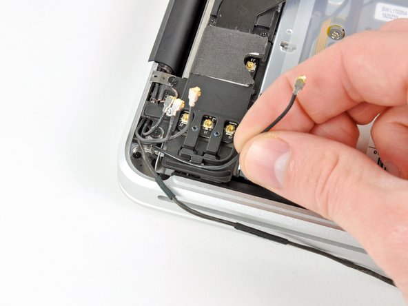
- Disconnect the four antenna connectors boxed in red in the first picture.
- To do so, use the tip of a spudger to pry their connectors up from the sockets on the AirPort/Bluetooth board.
- De-route each of the cables from their channels in the AirPort/Bluetooth bracket.
- Remove the following five screws:
- Two 10.3 mm Phillips screws
- Two 3.1 mm Phillips screws
- One 5 mm Phillips screw
- Pull the AirPort/Bluetooth assembly and the Subwoofer upward near the center of the side of the optical drive until they clear each other.
- Remove the AirPort/Bluetooth board assembly.
- Remove the three 2.7 mm Phillips screws securing the optical drive to the upper case.
- Lift the optical drive from the edge nearest the display and remove it from the upper case.
- Peel the right speaker cable off the upper case.
- Use a plastic opening tool or another thin prying object to carefully pry the right speaker up from the adhesive securing it to the upper case.
- Start prying up from the edge of the right speaker nearest the display. Starting from the other side may damage one of the antennas.
- Pry up along the edge of the right speaker until it is separated from the upper case.
- Pull the right speaker out from under the optical drive opening.
- Remove two of the three 6 mm T8 Torx screws securing the right side of the display to the upper case.
- We purposely have you leave one screw attaching the display to the upper case to aid in future steps.
- Remove the small piece of foam tape covering the left display hinge screws.
- Remove two of the three 6 mm T8 Torx screws securing the left side of the display to the upper case.
- We purposely have you leave one screw attaching the display to the upper case to aid in future steps.
- Open your MacBook Pro so the display is perpendicular to the upper case.
- Place your opened MacBook Pro on a table as pictured.
- While holding the display and upper case together with your left hand, remove the remaining T8 Torx screw from the lower display bracket.
- Be sure to hold the display and upper case together with your left hand. Failure to do so may cause the freed display/upper case to fall, potentially damaging each component.
- Remove the last remaining T8 Torx screw securing the display to the upper case.
- Grab the upper case with your right hand and rotate it slightly toward the top of the display so the upper display bracket clears the edge of the upper case.
- Rotate the display slightly away from the upper case.
- Lift the display up and away from the upper case, minding any brackets or cables that may get caught.
- Upper case remains.