MacBook Pro 13" Unibody Early 2011 Display Replacement
ID: 5140
Description: Use this guide to replace a broken display...
Steps:
- Remove the following ten screws:
- Three 14.4 mm Phillips #00 screws
- Three 3.5 mm Phillips #00 screws
- Four 3.5 mm shouldered Phillips #00 screws
- When replacing the small screws, align them perpendicular to the slight curvature of the case (they don't go straight down).
- Use your fingers to pry the lower case away from the body of the MacBook near the vent.
- Remove the lower case.
- Use the edge of a spudger to pry the battery connector upwards from its socket on the logic board.
- It is useful to pry upward on both short sides of the connector to "walk" it out of its socket. Be careful with the corners of the connectors, they can be easily broken off.
- Bend the battery cable slightly away from its socket on the logic board so it does not accidentally connect itself while you work.
- Use the flat end of a spudger to pry the AirPort/Bluetooth ribbon cable connector up from its socket on the logic board.
- Carefully pull the camera cable out of its socket on the logic board.
- Pull the cable parallel to the face of the logic board. Pulling it upward may damage the logic board or the cable itself.
- Carefully move the AirPort/Bluetooth ribbon cable out of the way as you peel the camera cable off the adhesive securing it to the subwoofer and the AirPort/Bluetooth bracket.
- De-route the camera cable out from under the retaining finger molded into the AirPort/Bluetooth bracket.
- Use the tip of a spudger to pry the antenna connector closest to the logic board up from its socket on the AirPort/Bluetooth board.
- De-route the antenna cable from under the finger molded into the AirPort/Bluetooth bracket.
- Using the method described in the last step, disconnect the remaining three antenna connectors.
- De-route their cables from the slots cut in the AirPort/Bluetooth bracket.
- Remove the following five screws:
- Two 10.3 mm Phillips screws
- Two 3.1 mm Phillips screws
- One 5 mm Phillips screw
- Pull the AirPort/Bluetooth assembly and the Subwoofer upward near the center of the side of the optical drive until they clear each other.
- Remove the AirPort/Bluetooth assembly, minding the fragile antenna contact near the corner of the upper case.
- Remove two of the three 6 mm T8 Torx screws securing the right side of the display to the upper case.
- We purposely have you leave one screw attaching the display to the upper case to aid in future steps.
- Grab the plastic pull tab secured to the display data cable lock and rotate it toward the DC-In side of the computer.
- Pull the display data cable straight out of its socket on the logic board.
- Do not lift up on the display data cable, as its socket is very fragile. Pull the cable parallel to the face of the logic board.
- Remove the following two screws:
- One 8.6 mm Phillips screw
- One 5.5 mm Phillips screw
- Remove the display data cable retainer from the upper case.
- Remove the piece of foam tape covering the display screws near the MagSafe DC-In board.
- Remove two of the three 6 mm T8 Torx screws securing the left side of the display to the upper case.
- We purposely have you leave one screw attaching the display to the upper case to aid in future steps.
- Open your MacBook Pro so the display is perpendicular to the upper case.
- Place your opened MacBook Pro on a table as pictured.
- While holding the display and upper case together with your left hand, remove the remaining T8 Torx screw from the lower display bracket.
- Be sure to hold the display and upper case together with your left hand. Failure to do so may cause the freed display/upper case to fall, potentially damaging each component.
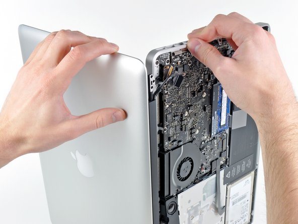
- Remove the last remaining T8 Torx screw securing the display to the upper case.
- Grab the upper case with your right hand and rotate it slightly toward the top of the display so the upper display bracket clears the edge of the upper case.
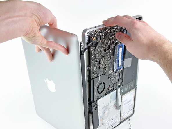
- Rotate the display slightly away from the upper case.
- Lift the display up and away from the upper case, minding any brackets or cables that may get caught.