Panasonic Lumix DMC-F7 Replacing LCD Screen Replacement
ID: 5015
Description: If you’ve cracked the screen or are...
Steps:
- Slide the lock switch to the right so that it is in the unlocked position.
- Use your finger to slide the battery hatch in the direction of the downward arrow so that the hatch is open.
- Both battery and memory card should now be visible.
- Open the battery hatch and then the black cover to expose the battery compartment.
- The camera used to create these repair guides did not have a battery and memory card.
- Remove the battery.
- When installing the new battery, ensure it is in the same orientation as before.
- Using the Phillips #00 screwdriver, remove the two 2.8 mm screws located under the hatch.
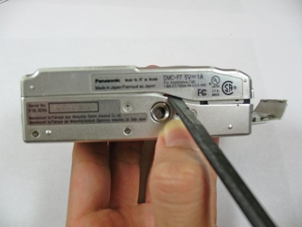
- Use the Phillips #00 screwdriver to remove the three 2.8 mm screws on the bottom of the camera.
- Use the Phillips #00 screwdriver to remove the two 2.8 mm screws on the side of the camera.
- Use a spudger to pry open the case at all sides.
- Be careful not to damage the ribbon cable when opening. Ensure it is still attached.
- Use your fingers to carefully remove the back casing from the front of the camera.
- Place the camera on a flat surface with the front side facing down.
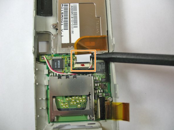
- Use the spudger to flip up the retaining flap and slide the ribbon cable out of the connector.
- Hold down on the camera's metal casing with one hand. Using your other hand, remove the back case from the rest of the camera.
- Use a spudger to lift the screen ZIF connector tab.
- Use the back of the spudger to push the ribbon cable free.
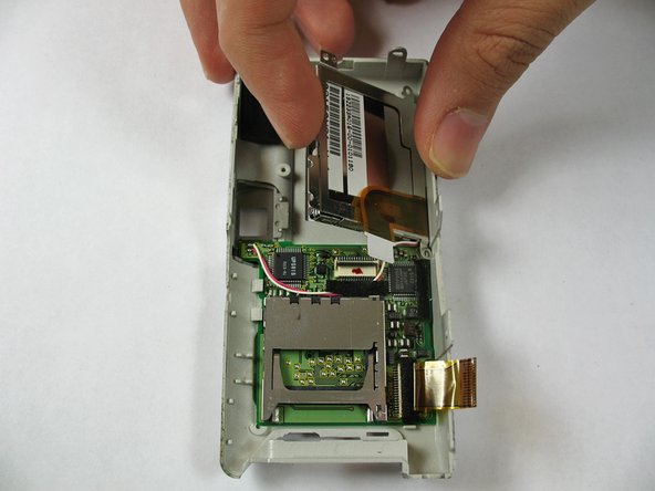
- Use the screwdriver to remove the four 2.4 mm Phillips screws.
- Lift up the LCD screen from the front case.
- Potential for device damage: The wire is still connected to the board in the other side.
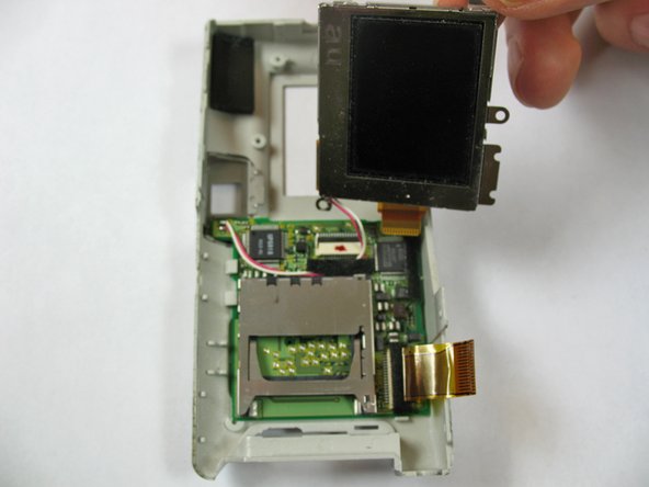
- Remove the LCD screen from its case.
- Locate the wire connecting the LCD screen to the motherboard.
- Use the soldering iron to desolder the wire.
- Use the soldering iron to solder wires from new LCD screen to the circuit board.