Nikon Coolpix S210 Circuit Board Replacement
ID: 4982
Description: You will be desoldering the circuit board of...
Steps:
- Place thumb on the battery cover panel on the bottom of the device.
- Slide the panel to the right away from the camera.
- Slide the orange latch outward towards the corner of the camera.
- The battery should pop out.
- Remove the battery and reattach the cover.
- After removing the battery, unscrew the four 3.10mm screws on the side opposite the buttons.
- Unscrew the three 4.05mm screws on the bottom of the camera below the lens.
- Unscrew the two 4.05mm screws on the side next to the buttons.
- Gently wedge the flat end of the spudger between the back case and the wrist-strap mount.
- The wrist-strap mount is the thin metal piece on the side of the camera. Your camera may have the wrist-strap attached, but you will not need to remove it to continue.
- Carefully pry the back case away from the camera and then gently lift it off.
- Having removed the back case, the LCD screen should be sitting loosely on the camera, attached only by a wide ribbon and a narrow ribbon.
- The ribbons are connected to and held in place by small plastic latches.
- To remove the wide ribbon, gently pry the spudger underneath the black plastic latch where the ribbon connects and lift up. The ribbon should slide out easily.
- Repeat the same process with the smaller ribbon, this time looking for a light blue latch.
- Gently remove the LCD screen.
- After removing the LCD screen, unscrew the four 3.8mm screws that hold down the metal plate
- Unscrew the 2.5mm screw next to the wrist-strap mount.
- Position the camera with the lens facing down and the shutter button facing you.
- Lift the metal plate away from the camera without removing it fully. There is a ribbon attaching the edge of the plate to the camera.
- The ribbon is being held in place by a black latch.
- Carefully pry the spudger under the black latch and lift gently upward. The ribbon will slide out easily.
- With the ribbon unlatched, the entire metal plate should now be detached.
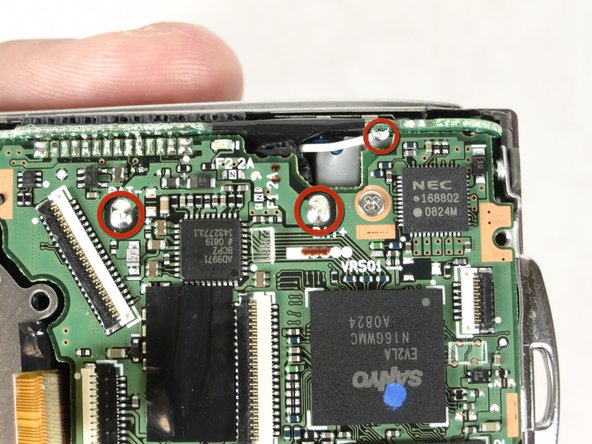
- Desolder the marked areas. For desoldering instructions go -here-
- Place the spudger underneath the small black tape as shown. Gently lift the spudger up to remove the tape.
- Remove the 3.8mm screw from the circuit board.
- Desolder the marked areas.