Removing Olympus FE-210 Motherboard
ID: 4949
Description: Before removing the Motherboard you must first...
Steps:
- The battery compartment is located on the bottom side of the camera. Push the button in, and slide the cover to get access to the batteries.
- The batteries will slide right out.
- When putting new batteries in, make sure they are pointing the right direction.
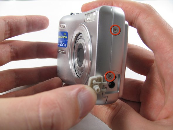
- Remove the 7 screws holding the front case in place, with a #00 screwdriver.
- Six screws are 3.6 mm.
- The seventh screw is 3.2 mm.
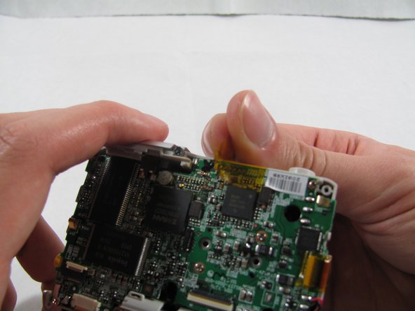
- Pulling the front case off, requires applying enough strength in the right areas.
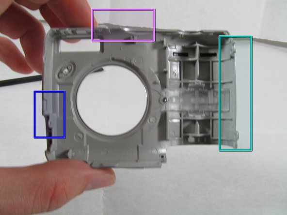
- The front case snaps into place in three places:
- At the top and bottom of the battery side (opposite of side pictured) of the case.
- Right in the middle of the DC-in side (side pictured) of the case.
- Top of the camera, to the left of the power button.
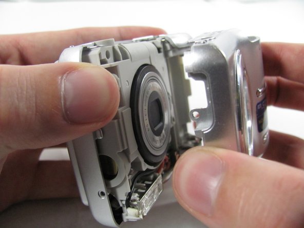
- Once those places are disconnected, the front case will pop right off.
- The camera in the first two pictures is upside down. This is the best position to place your thumbs to remove the case.
- Remove the 3.2 mm screw in the battery compartment using a #00 screwdriver.
- After removal of the screw the case will be loose, but do not tug it off. There is a cord connecting the rear controls to the motherboard.
- Carefully pull the rear case away from the camera until you have access to the cord connected to the motherboard.
- Lift the white latch using a fingernail or a spudger.
- Pull the cord from its connector.
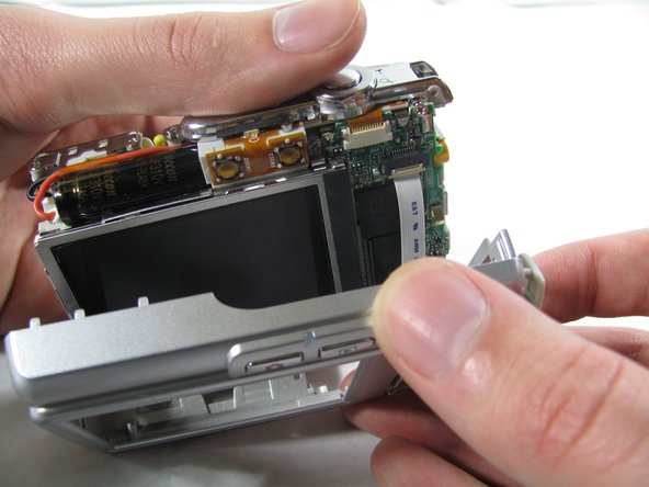
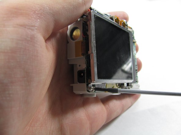
- Remove the two 2.7 mm screws using a #00 screwdriver.
- After removing the screws the display will be free. Do not remove it. Like the rear case, there is a cord connecting it to the motherboard that must be disconnected first.
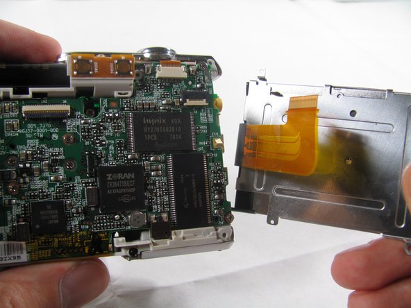
- Using a spudger, lift the latch on the connector.
- Remove the ribbon cord from its connector.
- Remove the LCD from the rest of the camera.
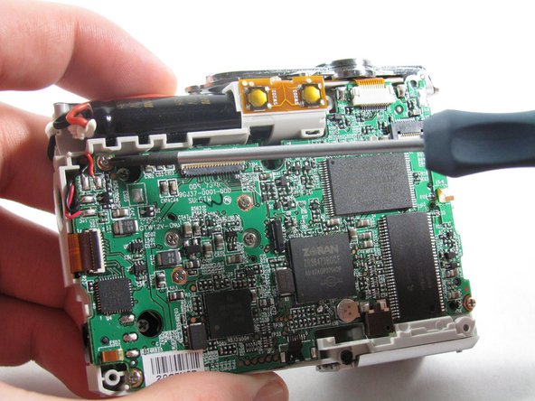
- Remove the 2 pieces of translucent yellow tape.
- Removing these pieces of tape will void the camera warranty. They serve no functional purpose and do not need to be replaced during reassembly.
- Remove the seven 2.7 mm using a #00 screwdriver.
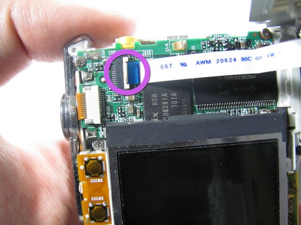
- Remove the ribbon cord located near the top right corner of the motherboard. Do this by carefully pulling the cord out of the socket using a pair of tweezers.
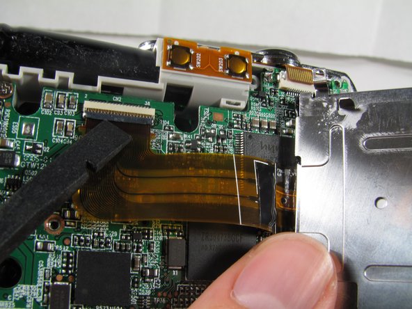
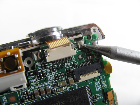
- Disconnect the ribbon cord located on the left side of the motherboard.
- Use tweezers or a spudger to lift the latch on the connector.
- Carefully remove the cord from the connector.
- De-solder the 2 connection points.
- Be careful to not damage any part of the circuit board with the soldering iron.
- Remove the motherboard from the camera casing.