Nintendo Entertainment System Motherboard Replacement
ID: 3828
Description: If the motherboard is broken, then follow our...
Steps:
- Remove the six 13.25mm Phillips screws on the bottom of the game console with a #2.5 flathead screwdriver.
- The screws are recessed about 40 mm.
- Flip the game console right side up and take off the top by pulling it up and away from the rest of the device with your hands.
- Remove the seven 13.25mm Phillips screws from the metal cover with a Phillips head #2 screwdriver.
- Remove the metal cover by pulling it up and away from the rest of the console with your hands.
- Remove the two silver 17.45mm Phillips screws from the cartridge tray using a Phillips head #2 screwdriver.
- Remove the two bronze 13.25mm Phillips screws from the cartridge tray using a Phillips head #2 screwdriver.
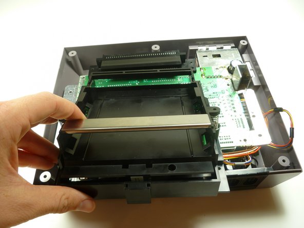
- Slide the cartridge tray toward you, away from the 72-PIN connector, and off the motherboard assembly.
- Note: Underneath the cartridge tray is a black trapezoid-shaped tab/lip (see marker). When properly assembled this tab/lip goes below the motherboard and shielding as seen here.
- During reassembly, make sure you orient this tab underneath the motherboard in addition to orienting the tray on top. Failure to do so will bow the cartridge tray and place stress on the component, causing the cartridge spring mechanism to bind.
- Remove the three 13.25mm Phillips screws that secure the motherboard to the lower case with a Phillips head #2 screwdriver.
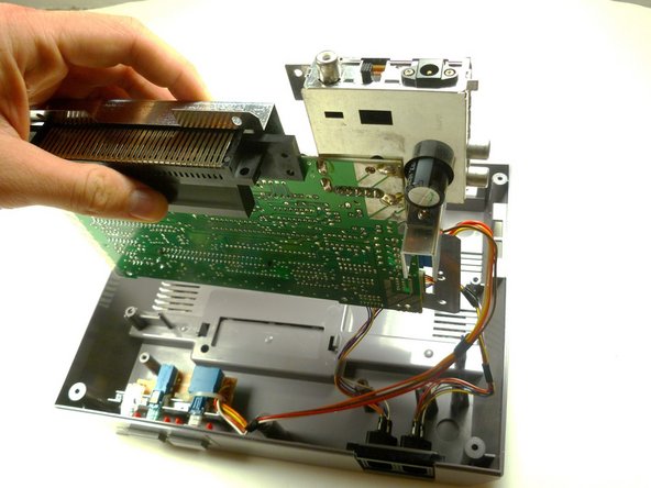
- Pull the motherboard assembly straight up and out of the plastic case with your hands.
- Turn the motherboard assembly over so the metal cover is facing you.
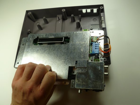
- Disconnect the wire harnesses from the motherboard assembly:
- Controller 1 (left)
- Controller 2 (right)
- Power
- To prevent mixing the wires up during reassembly, it can be helpful to label the wires with a piece of tape.
- Lift off the EMI shield (metal cover) from the motherboard assembly.
- Turn over the motherboard assembly so the 72-PIN connector is on the top of the motherboard assembly.