Panasonic Lumix DMC-TZ5 Flash Unit Replacement
ID: 3808
Description: The flash unit is attached to the inner casing...
Steps:
- Remove the battery and memory card from the device.
- Remove 4 screws from the right side of the camera.
- There are two 3.4mm screws at the top.
- There are two 2.2mm screws at the bottom.
- Remove the single 3.4mm screw on the left side of the camera.
- Remove 5 screws from the base of the camera.
- There are two 2.2mm screws next to the battery compartment.
- There are three 4mm screws around the tripod mount.
- Slowly slide the back cover away from the device
- The back casing is held in place by two ribbon cables. Do not pull the back cover too far from the camera.
- Detach both ribbon cables using a spudger.
- Use the tip of the spudger to lift the black clip upward, unlocking the ribbon cable.
- Remove the back casing from the camera.
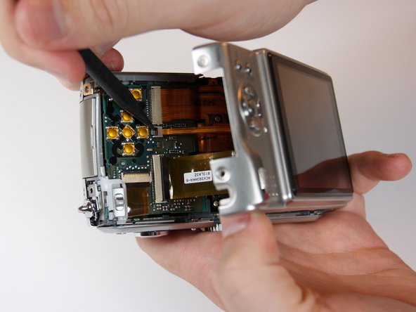
- Use the spudger to remove the ribbon cable connecting the lens casing to the circuit board by lifting up the black clip.
- Carefully remove the function switch cover. This unit snaps on and off.
- Carefully unsnap the front logic board from the rear logic board using a spudger.
- Slide the entire top part of the camera that is attached to the logic board, horizontally away from the camera.
- This step is only necessary if you want to separate the upper part from the button board.
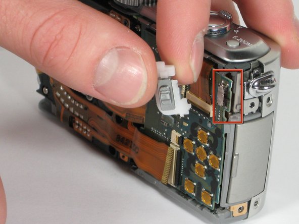
- Remove the ribbon cable from the top connection panel by unlocking the black clip with a spudger.
- This leaves you with the logic board and the top connection panel separate and free from the camera
- Use a spudger to detach the ribbon cable from the circuit board. Lift the black clip up to unlock it as before.
- Remove the 3 screws holding the lens assembly in place.
- The two screws on the left are 4.5mm with washers.
- The single screw on the right is 4mm.
- Push the lens assembly slightly toward the circuit board, and pull the left side out of the casing first. You will have to wiggle this out gently.
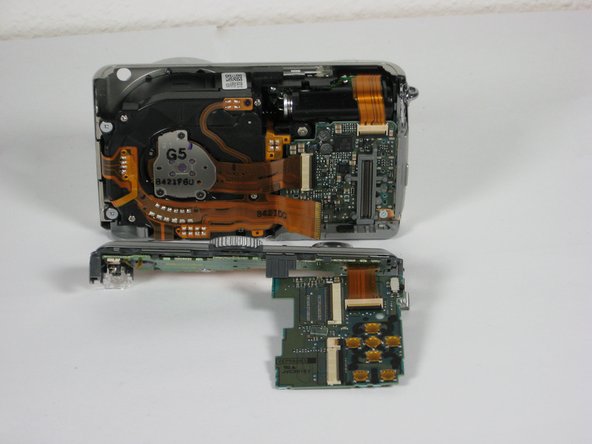
- Remove the entire assembly out of the casing.
- The ribbons on the left and bottom of the assembly simply rest on the camera housing.
- Use the spudger to unclip the top ribbon cable from the circuit board.
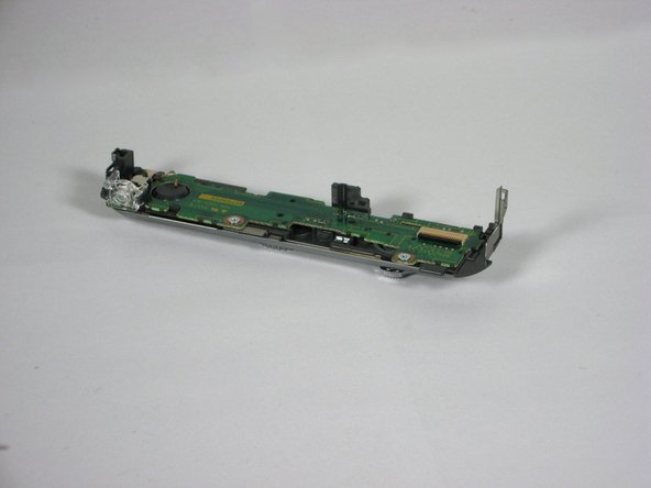
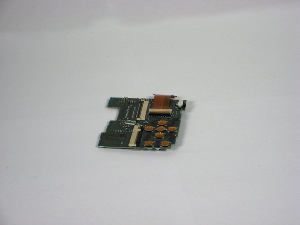
- Remove the single 2mm screw in the bottom right corner of the circuit board
- Gently slide the circuit board out away from the port connections. Pull it toward where the lens used to be. Some wiggling may be necessary to remove.
- The circuit board is fitted into slots attached to the side of the camera. Do not angle upwards to remove.
- Take note of how the slots fit into the circuit board for easy replacement.
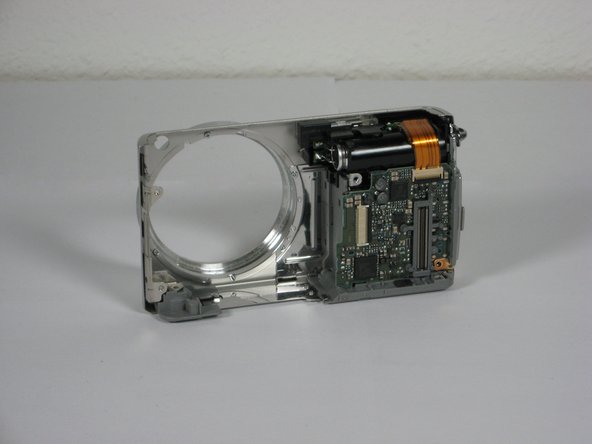
- After removing the AV circuit board you are left with the front casing attached to the inner casing and flash unit.
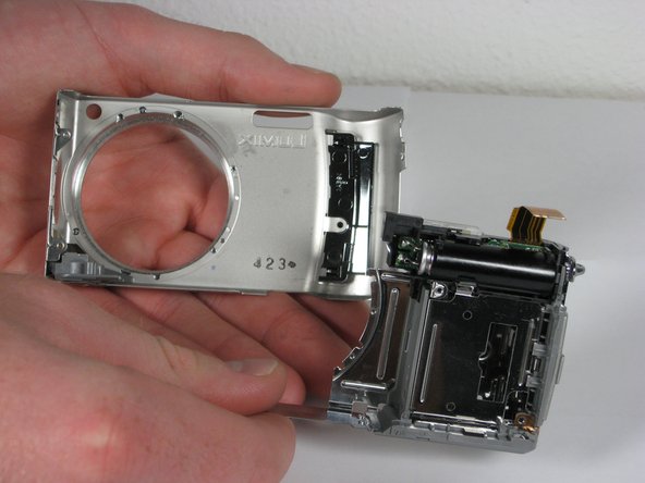
- First you must remove two 3.5mm blue screws near the hole of the lens that attach the inner casing.
- Remove the 3.5mm colorless screw that lays within the square opening of the inner casing.
- Remove the front casing from the rest of the device.
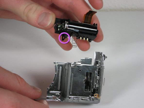
- Use a spudger to carefully lift the small clip located to the left of the unit.
- Lift the flash unit out of the case.