Sony Cyber-shot DSC-W55 Motherboard - Second Half Replacement
ID: 3772
Description: We will provide instructions to follow to...
Steps:
- Slide the battery cover in the direction the arrow points.
- Pull the battery cover towards you.
- Flick the blue switch for the battery to pop out.
- Remove the battery from the camera.
- Using the Phillips #00 screwdriver, remove the two screws from the caution panel.
- Remove that panel.
- Careful for falling pieces.
- Remove the screw with a Phillips #00 screwdriver from the left side of the camera (with '3x optical zoom' engraved on the side panel).
- Remove the panel.
- Remove the screw using the Phillips #00 screwdriver from the bottom of the camera, closest to the back cover.
- Gently remove the back cover.
- It may be a bit stiff, so use some force to remove it. Proceed with caution.
- Remove the screw using a Phillips #00 screwdriver on the right side (where the caution panel used to be).
- Remove the small screw using a Phillips #00 screwdriver on the bottom of the camera attached to the front cover.
- Gently remove the front cover.
- Put a little force to pop off the case. Proceed with caution.
- Flip the black secure locks off. Tweezers may be necessary.
- Detach the two orange cables.
- Gently pull the lens container out of the camera.
- Remove the black screw using a Phillips #00 Screwdriver on the motherboard.
- Remove the two orange cables on the top of the motherboard with tweezers.
- Lift the motherboard out of its slot.
- For the AV port, detach the bottom orange cable.
- For the LCD screen, detach the top orange cable on the right side of the motherboard.
- For the motherboard, detach all the orange cables.
- Careful not to damage the red, white, and black wires when lifting the board.
- Verify the orange cables from the motherboard are removed from the LCD screen.
- Lift the LCD screen off the hinge.
- Verify that the LCD screen is attached to the chip on the back on the camera.
- Remove the dial from the back of the camera. It pops right off very easily.
- Remove the screw using a Phillips #00 Screwdriver from the camera.
- Remove the orange cable that is attached between the top of the camera and the chip. It should slide straight out with a little bit of force.
- Remove the chip and the LCD screen now from the camera.
- The chip may need a slight upward tug with a fingernail or tweezer.
- Verify that the orange cables from the top piece are removed from the motherboard.
- Remove the screw using a Phillips #00 Screwdriver on the upper part of the back side.
- Pull the top off slowly and with caution. It is still slightly attached and may need a little force.
- Slowly twist out the flash assembly.
- It is attached to the hinge so a little force is necessary.
- Verify the red, white, and black cables are still attached to the camera.
- Remove the screw using a Phillips #00 Screwdriver near the AV port
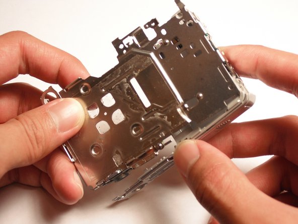
- Remove the bottom part of the camera (where the battery is inserted into).
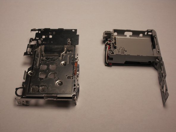
- This should detach the rest into two pieces. Place the other aside.
- To remove the crimps, use the spudger to push into gold part of the crimp and pull the wire out gently.
- Careful not to break the crimps from the wires.
- Remove the motherboard from the camera.