Samsung S860 Motherboard Replacement
ID: 2541
Description: The motherboard of your Samsung S860 camera...
Steps:
- With the camera facing LCD side up, slide the battery compartment lid to the right.
- Remove the old batteries.
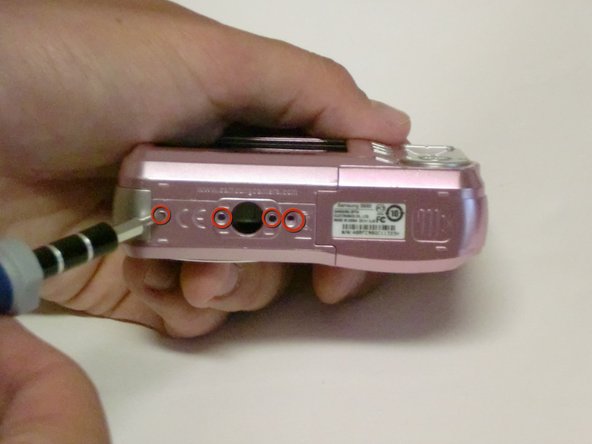
- Remove all screws along the edges of the camera, using a #00 Phillips screwdriver.
- Slide open the battery compartment cover before removing the exterior covers of the camera.
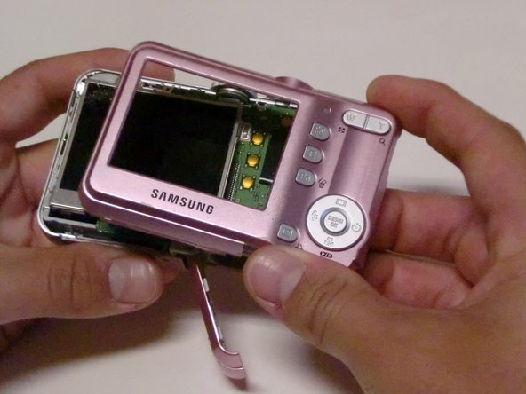
- Carefully pull the back case (the side showing the LCD screen) away from the front half.
- There are clips securing the top of the back case. Do not be afraid to use the proper amount of force to remove the back case.
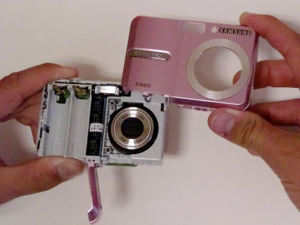
- Turn the camera around to the front (the lens side). Carefully remove the front case.
- There are also clips on the lens' side as well, so do not be afraid to use force.
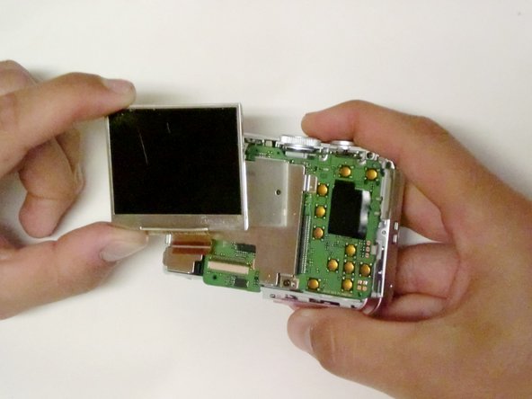
- Position the camera so the LCD screen is facing you.
- Remove the LCD screen from the screen plate.
- Replace the broken LCD screen with the functioning LCD screen.
- Using a #00 Phillips screwdriver, remove the six 4.3 mm screws along the edges of the camera.
- Save them for putting the camera back together.
- Turn the bottom edge of the camera towards you.
- Slide open the battery chamber.
- This must be done to remove the exterior covers of the camera.
- Carefully pull the back of the camera (the LCD screen side) away from the front.
- Turn the camera to the front (the flash side) and pull the case off.
- There are clips on both sides of the case that secure it to the camera, so you may need to use a bit of force to remove the case.
- Orient the camera so the LCD screen is facing you.
- Remove any tape holding the screen down.
- Lift the LCD screen from the screen plate.
- Lift the hinged lip on the camera body where the ribbon cable enters the connector.
- Remove the ribbon from the logic board by gently pulling it straight out.
- Try not to kink or crease the cable.
- Using a #00 Philips screwdriver, remove the two 4.5 mm screws from the screen plate.
- Separate the screen plate and logic board.
- Locate the brown ribbon cable attached to the upper left edge of the logic board.
- Remove this ribbon by gently pulling in the opposite direction of the logic board.
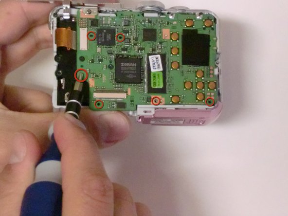
- Using a #00 Philips screwdriver, remove the three 3.32 mm screws connecting the logic board to the camera.
- Separate the logic board and the core of the camera.
- Separate the logic board by carefully pulling the logic board away from the camera.
- Be careful not to damage the battery compartment. The battery sensors are attached to the logic board, so be gentle.
- The USB connector is going to want to hang up on the housing, but once you have that free, the battery leads will slide out relatively easily.