iBook G4 14" 933 MHz-1.33 GHz DC-In Board Replacement
ID: 182
Description: Tripped over your power cord? At least you...
Steps:
- Use a coin to rotate the battery locking screw 90 degrees clockwise.
- Lift the battery out of the computer.
- Use a pin (or anything you like) to remove the three rubber feet from the lower case.
- Remove the three newly-revealed Phillips screws.
- Use a spudger or small flathead screwdriver to pry up the three metal rings that housed the rubber bumpers.
- Remove the three hex screws using a T8 Torx screwdriver (or Allen screws using an Allen key if these are used).
- The shorter screw is in the center of the computer.
- Remove the two Phillips screws on either side of the battery contacts.
- Breathe deeply. Trying times are ahead, but we promise the lower case does come off.
- Push the thin rims of the lower case surrounding the battery compartment in, bending them past the tabs, and then lift up to free that corner of the lower case.
- There is a slot on the wall of the battery compartment that locks the lower case in place. Use a small flathead screwdriver to pry out the slot's lower rim and pull up on the lower case to free the slot from the tabs holding it.
- Be careful not to break this clip!
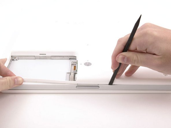
- Run a spudger along the seam between the lower case and upper case on the front of the computer to free the tabs locking the lower case. Pull up on the lower case and continue to use the spudger as necessary until you hear three distinct clicks.
- Continue to run the spudger around the front, right corner. There are two tabs on the port side of the computer, one near the front corner and one near the sound-out port.
- There are three tabs over the optical drive that must be released before the lower case can come off. Slide the spudger into the lower case above the optical drive and run it toward the back of the computer until you hear three distinct clicks.
- Once the front and sides of the lower case are free, turn the computer so that the back is facing you and pull the lower case up and toward you until the back tabs pop free (it may be helpful to jiggle the case up and down).
- Remove the small greasy springs with white plastic caps from either side of the battery contacts.
- Remove the following 10 screws from the bottom shield:
- Six 3 mm Phillips
- Three 7.5 mm Phillips
- One 14 mm Phillips
- Lift the bottom shield off.
- Remove the single Phillips screw securing the DC-In board.
- Disconnect the DC-In cable from the logic board.
- Deroute the cable from around the optical drive, removing tape as necessary, and angle the DC-In board out of its compartment.