RIM Blackberry 7290 Teardown
ID: 1281
Description: This is a teardown of the RIM Blackberry.
Steps:
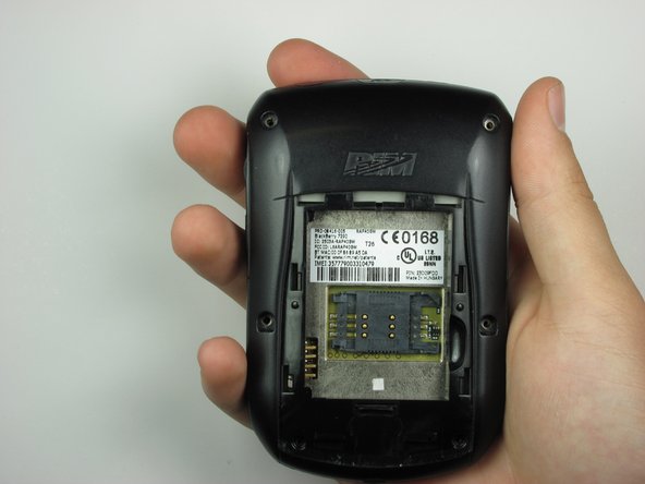
- Apply pressure to the lock button on the back of the device.
- Slide the battery cover down towards the bottom of the device, revealing the battery compartment.
- Locate groove along the right side of the battery compartment.
- Remove battery by prying between the battery and the groove.
- Slide the SIM card holder to the left to unlock the SIM card.
- Lift the SIM card holder up.
- Gently remove the SIM card from the SIM card holder by sliding the card along the railing.
- Locate the four screws along the perimeter of the back casing.
- Remove the four top screws using a T-6 torx screwdriver.
- The top four screws are .413 inches.
- Locate two screws within the lower edge of the inner compartment.
- Remove the two bottom screws using a T-6 torx screwdriver.
- The bottom two screws are .2 inches in length.
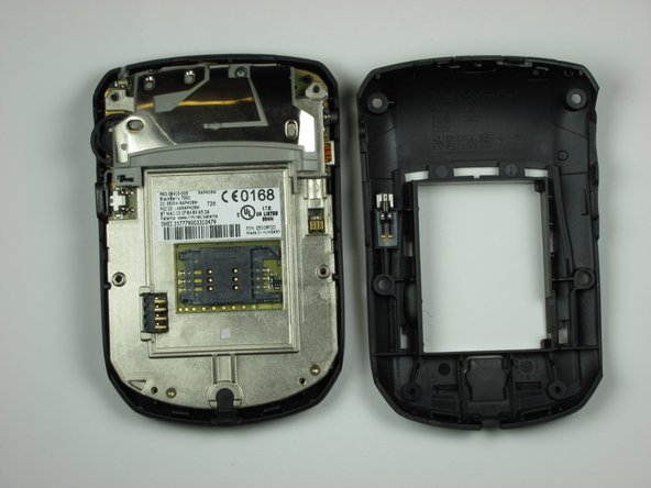
- The second picture displays the device after the six screws have been removed.
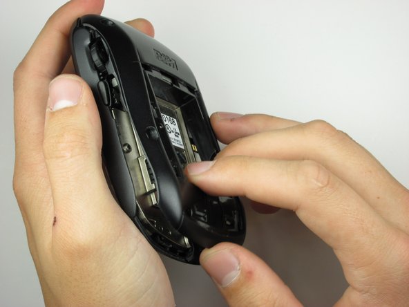
- Use the plastic opening tool to apply pressure on the two clips that are located at the bottom of the phone.
- Remove the back casing from the phone by lifting the unhooked portion, then slide the casing towards the top of the device.
- Make sure all clips holding the case together are unhooked, so no damage is caused to the case.
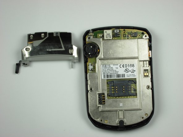
- Locate on the backside of the phone, a screw towards the top of the device.
- Using a T-6 screwdriver, remove the screw.
- After the screw has been removed, carefully lift the side button brace to reveal the side button.
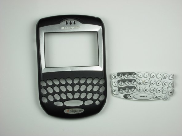
- To remove the phone's internals, start by loosening one side by pulling gently.
- With one side loosened, simply lift the phone internals to separate from the front casing.
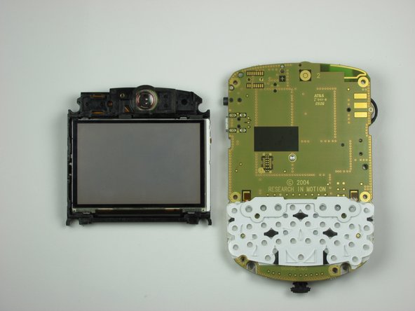
- Turn the internals over to reveal the LCD display.
- Peel off the rubber keypad buttons from the face plate.
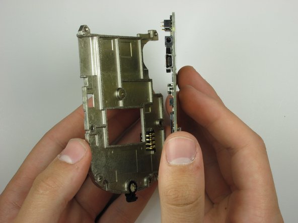
- Locate a hook on the right side of the internals below the volume wheel.
- Use a plastic opening tool to gently pry the hook, separating the LCD display from the logic board mounting plate.
- With the clip unhooked, gently separate the display from the phone internals by pulling.
- On the front side of the internals, locate the the three screws that are highlighted in red.
- Carefully remove screws from the internals, using a T6 torx screwdriver
- The screw is .2 inches in length.
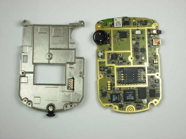
- Separate the logic board mounting plate from the logic board by lifting with minimal force.
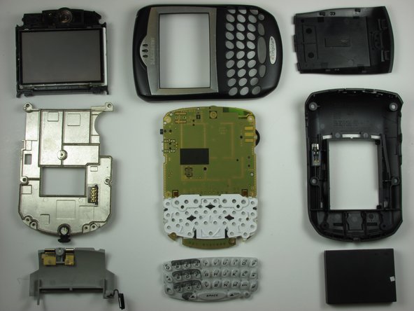
- These are all the components of the phone.