Sony VAIO VGN-T140P Teardown
ID: 1263
Description: As part of the Sony giveaway, I would like to...
Steps:
- Let's start with the tools and the victim...
- Remove the battery by moving the 2 release tabs.
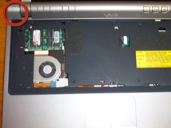
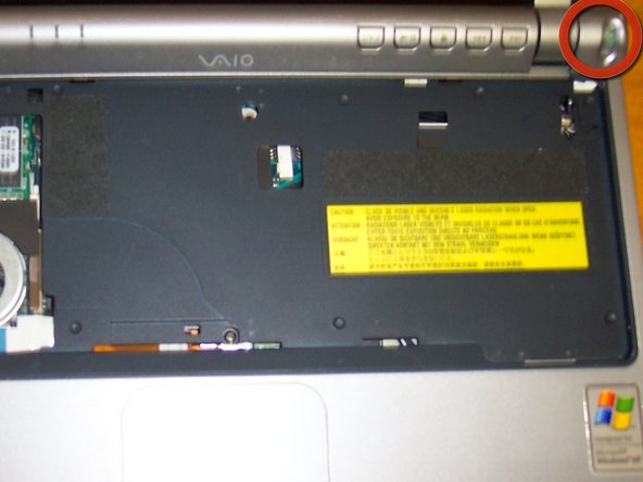
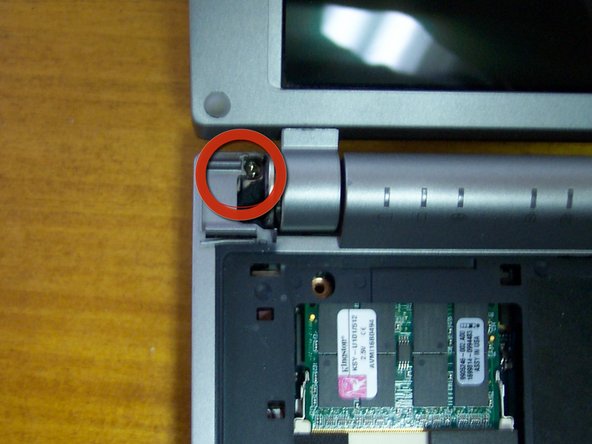
- Remove 3 screws holding the keyboard.
- Loosen 2 latches holding the keyboard down with the flat tip screwdriver, one by the F5 key, and the other by the Num Lock key. Move keyboard towards the touch pad and pull up.
- Remove the ribbon carefully.
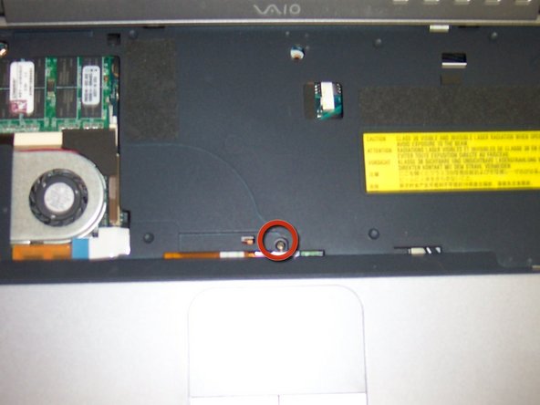
- I added this step separate for the ones that just want to upgrade the RAM.
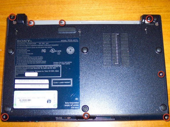
- Remove 8 screws under the computer.
- Remove the power button and cap on opposite side.
- Remove one screw from top and one from under cap opposite of the power button.
- Unsnap the top cover carefully around the edges.
- Disconnect 3 ribbons and pull top carefully towards the left side. Remove ribbon from the motherboard.
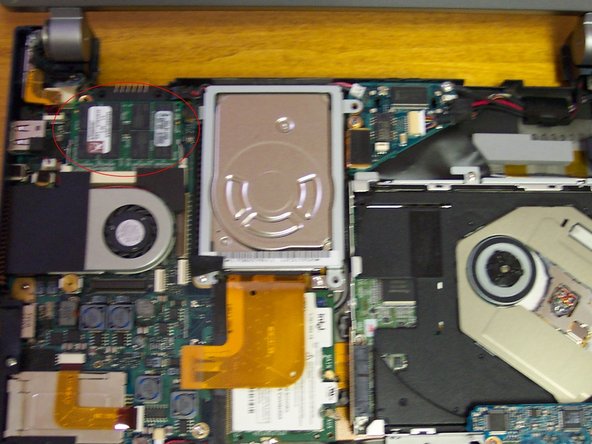
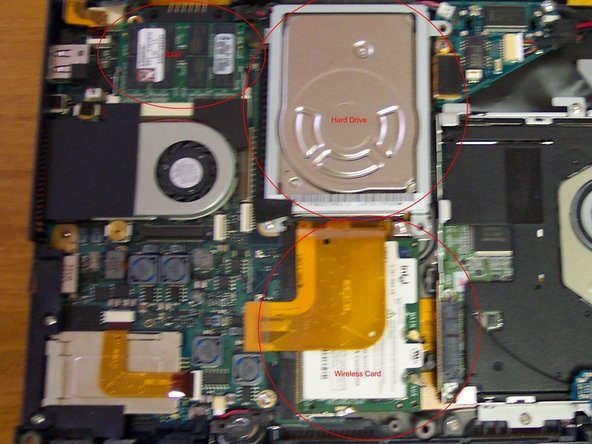
- Remove the RAM.
- Remove the RAM.
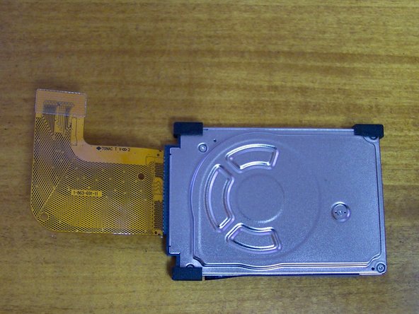
- Remove the hard drive metal bracket. Mine had 2 screws but I believe there are supposed to be 4 (lost them when I replaced the hard rive last time). Disconnect ribbon from motherboard.
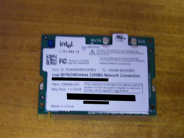
- Remove the wireless card. There are 2 antennas connected to it, the back wire goes on the main, gray on aux.
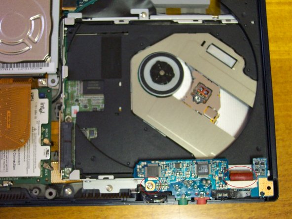
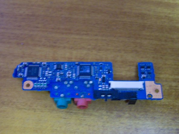
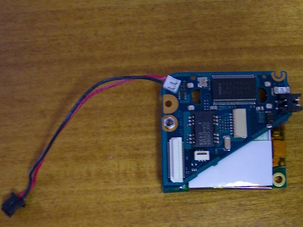
- Remove one screw form the sound card. Disconnect one ribbon and one connector (under) from card.
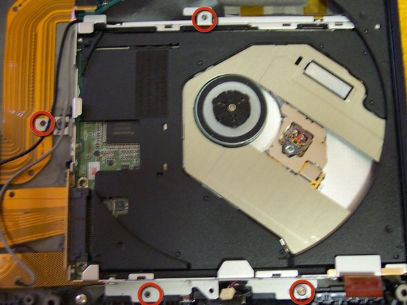
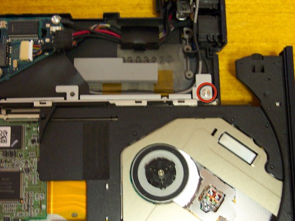
- Remove the DVD drive by unscrewing 5 screws, make sure to open the drive with the paper clip to access the last one.
- Remove one screw from the network/modem combo card. Disconnect 3 connectors and one ribbon from cards. There is an additional connector on the motherboard.
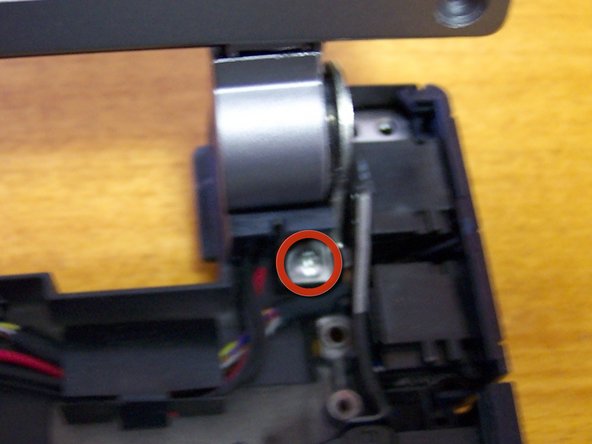
- Time to remove the screen. Remove 2 screws holding the hinges down
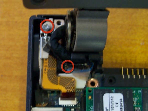
- Remove ground screw and wire.
- Remove 4 bezel screw covers. Remove 4 screws.
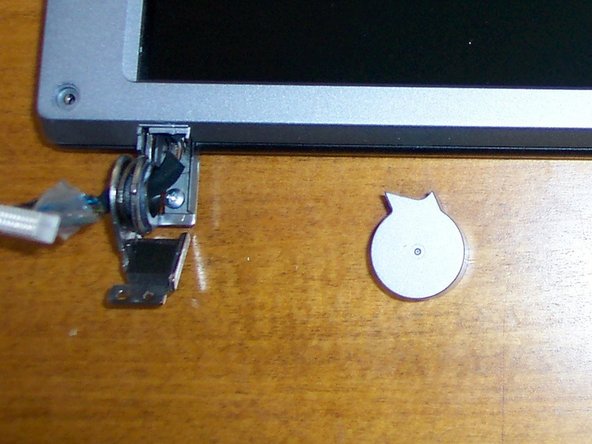
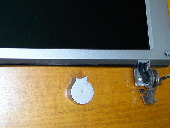
- Remove 2 caps from hinges. Remove bezel.
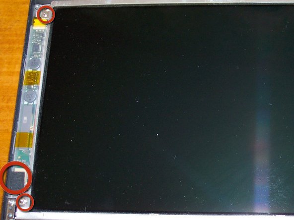
- Remove 4 screws holding screen. Disconnect one connector from the power module
- Disconnect one ribbon from the back of the screen.
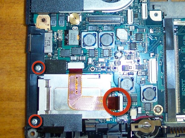
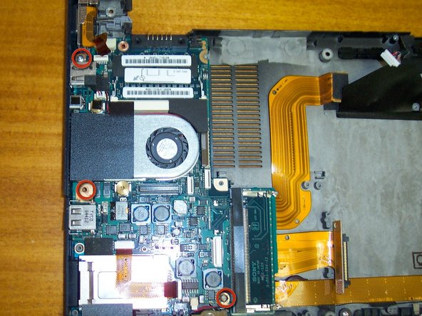
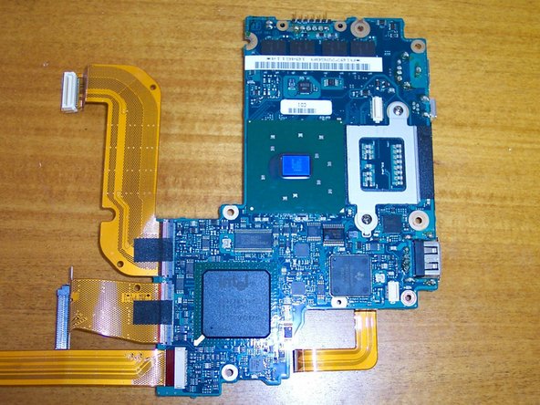
- At last, the motherboard. Remove 2 screws holding a plastic bracket down.
- Disconnect the ribbon connector and remove 3 screws.
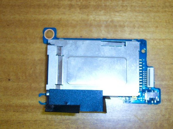
- Remove the memory stick reader.
- All done! Sorry for the crappy picture.
- Just in case you are wondering, is back together and working like a champ.