Sony Digital Projector VPL-ES1 Teardown
ID: 1229
Description: A multimedia LCD projector from Sony, the...
Steps:
- The Front view, Side view w/ Power input, Audio in, Coax in, VGA in and VGA out. Along with Zoom and Focus Dials
- The Bottom View
- First we are going to remove the Lamp by removing the screw in the first image, and opening and removing the door to the lamp
- Then we unscrew the two screws on the lamp. they do not completely disconnect from the lamp. So they will remain attached after unscrewing them.
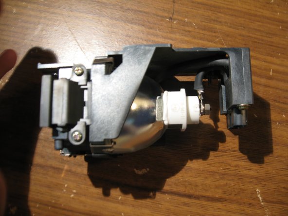
- Then lift up on Lamp Handle to remove Lamp from projector assmebly
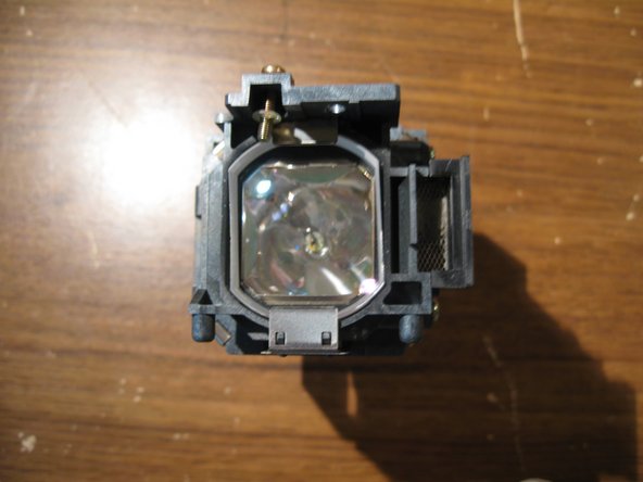
- A few pictures of the Lamp Removed from the Projector.
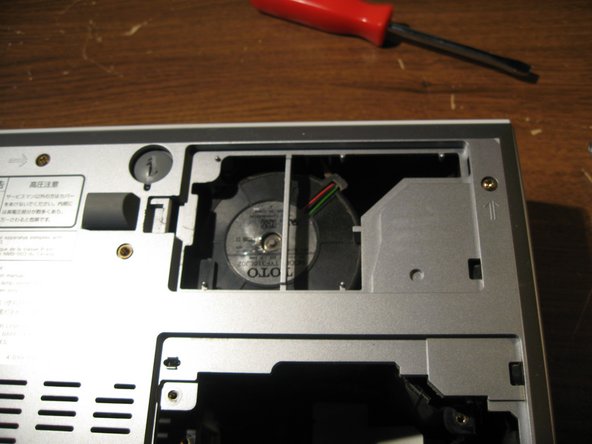
- Then simply pry up on the intake air door and remove
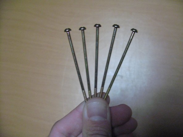
- At this point we will remove the six screws located on the underside of the unit.
- These are the long screws in the second photo here
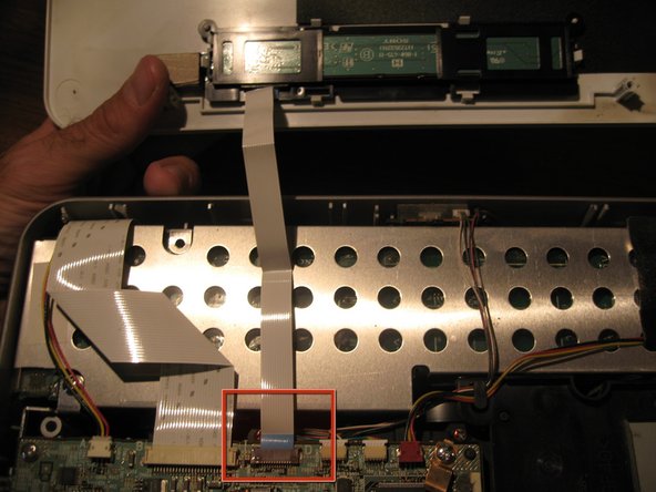
- Flip the unit over carefully and pry the case off working around the edges. Take note there is a ribbon cable that runs from the outer control panel to the mainboard.
- Pull ribbon cable from mainboard. Place top of unit to the side of your work area.
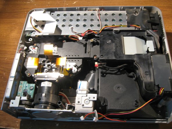
- First Look at the Inside
- Now you will remove all other connectors from the outer parts of the mainboard. as marked in the Red Rectangles. Gently, pull them out of their connection place.
- There is one connector from the mainboard to the little blue board in the bottom righthand corner that is connected on the underside of the mainboard. Just disconnect this one from at the blue board.
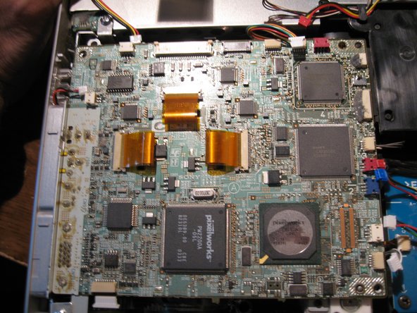
- You will find that the two connectors labeled in a yellow rectangle are not connected to anything leading me to believe that this mainboard may be used with other model projectors as well.
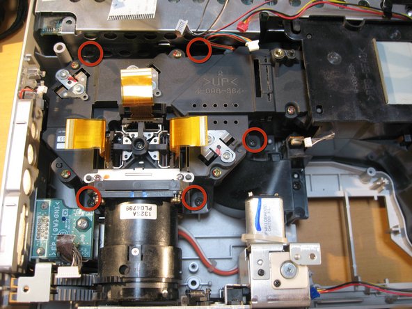
- Remove the five screws marked in the red Circles from the mainboard.
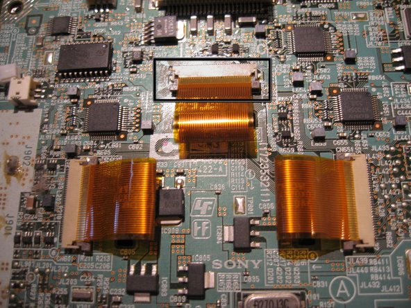
- In the Third image you will find the LCD Ribbon Cable on the Center of the Board. You will remove the three of the cables by gently pulling up on either side of the tiny brown connectors attching them to the board
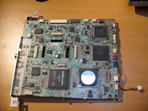
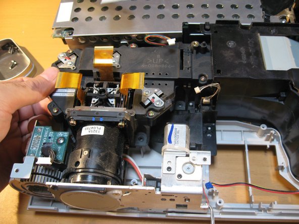
- Now to remove the mainboard. Gently pry outwards the Left side of the casing and lift the board up out of the Unit. Being carefull to watch the input connections near the side of the case.
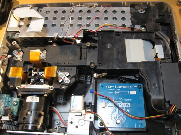
- Now the Mainboard has been removed
- have a look at some of our main components. The LCD and Prism connected to the Lens as well as some of the cooling Channels.
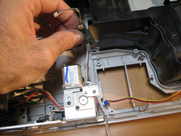
- You can opt to remove this little board from a fan shroud but i chose to leave it attached
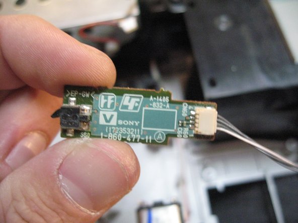
- I removed it to show you what it looks like anyway.
- I removed it to show you what it looks like anyway.
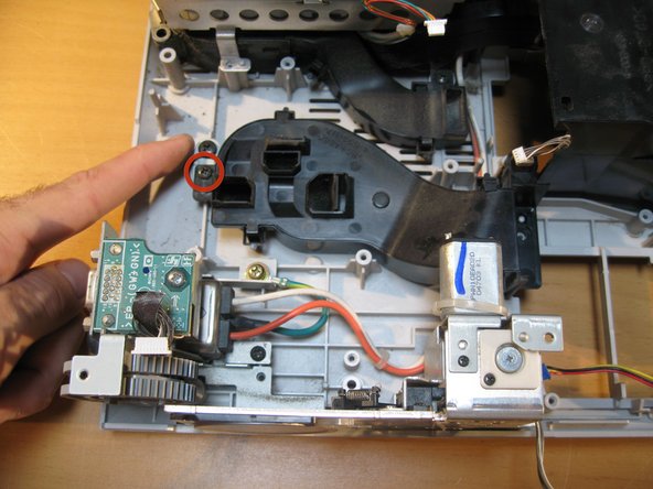
- Remove screw marked in red
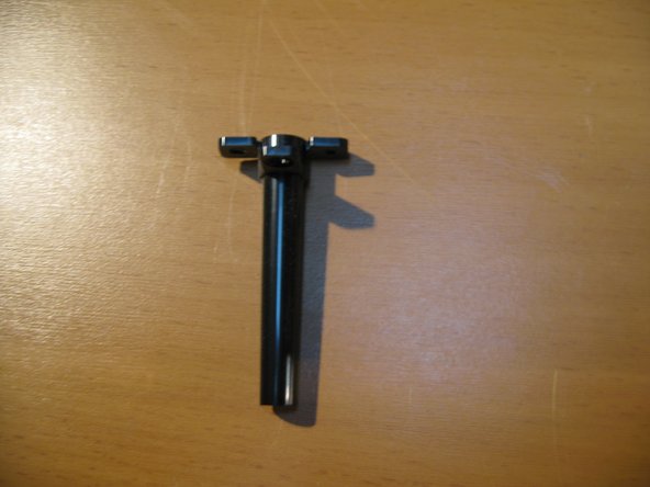
- This appears to be something that holds the board up for some reason that is beyond me?
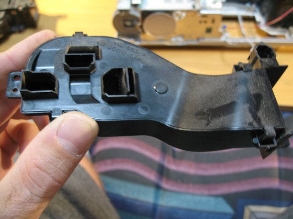
- And a picture of it removed
- Remove the two screws that run from the power supply to the lamp
- Pull out the connector
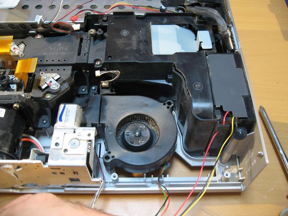
- There are three Screws to be removed from the fan shroud in this step
- Remove Fan Shroud
- Now lift up and remove the fan
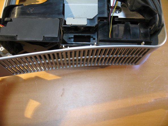
- To remove the side panel of the case- gently pry around the corners until removed
- A look at the side and rear panel of the case removed
- Now we Remove the 5 screws of the Mirror/LCD/Lens assembly
- And from the left side lift up on the Projection assmebly to remove from the unit
- Projection assembly removed
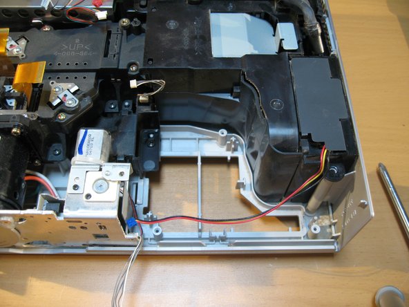
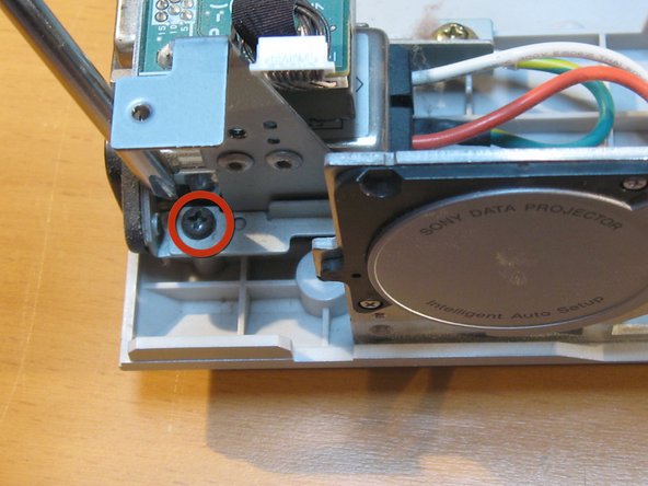
- Next remove the fan Channel by unscrewing one screw as labeled in red circle
- This piece i find rather interesting considering the job of the one fan is to route air particularly to the underside of the three LCD Screens for cooling
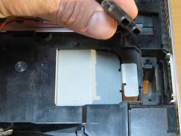
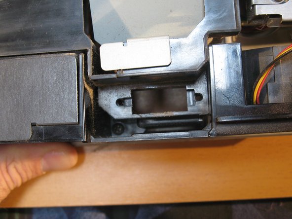
- Now there will be a tiny circuit switch upright after removing the fan channel.
- Remove simply by lifting out out placement niche
- This, I found is a neat little cutoff switch. Being that the little black switch is located at the underside of the unit in the Lamp assembly door. If the Switch is not depressed that means the door is not closed and power will not be applied to the lamp-Safety Feature
- Now we are going to look at removing the Automatic Lens door/Cap and Zoom/Focus Dials
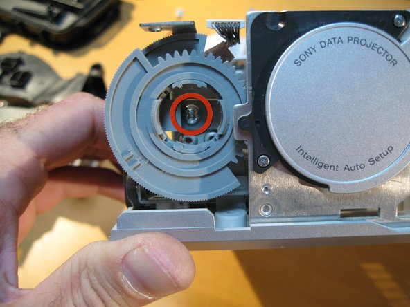
- We must remove the Zoom/Focus Dials first in order to proceed. Remove the one screw as labeled in the red circle. and gently remove the two dials out together
- Next to remove the screw holding the Autolens Cap to the rest of the unit.
- Now you can remove the Autolens cap with motor attached( on the right)
- The second image is just a view of what is left on the Unit from the left hand side.
- I am not going to remove the power supply nor the fan under it but i will give you these photos to admire. Power supplys can be dangerous people! So once again i will leave that as is.
- This 3rd pic has another interesting Fan channel from the left underside of the Power supply to the Lamp assembly in two different chutes.
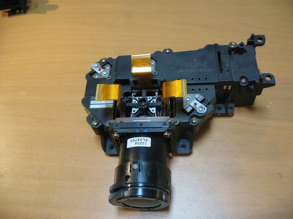
- Now onto the LCD Assembly - The heart of this projector.
- Shoot for the exhaust duct LUkE!
- The Beams of light get refracted by mirrors past the Lamp to focus three beams of light to the these LCD Screens and then onto the Prism which carries the image onto the lens - through the lens and onto the Wall / Ceiling / Barn of your choosing
- The underside of the LCD / Lens Assembly to show you the Cooling ducts leading up to the LCD panels. Neat huh?
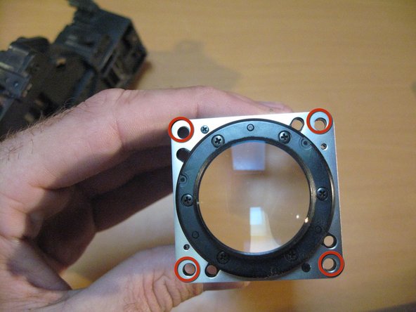
- The lens is removed by unscrewing the 4 screws located on the outer corners of the lens fixture.
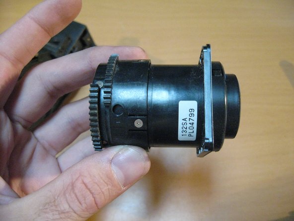
- New line.And a look at the lens by itself and it Zoom / Focus Ring Dials
- I am not going to dissasemble the lens-for good measure. Being I'm a not a Leica Tech. - it's most likely not one of their lenses anyway.
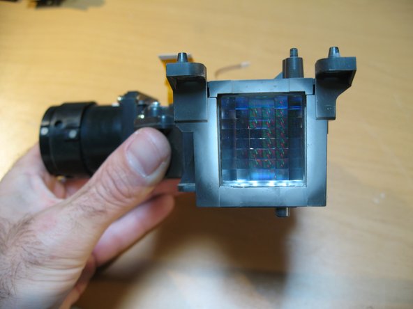
- A cool look inside the assembly minus the lens
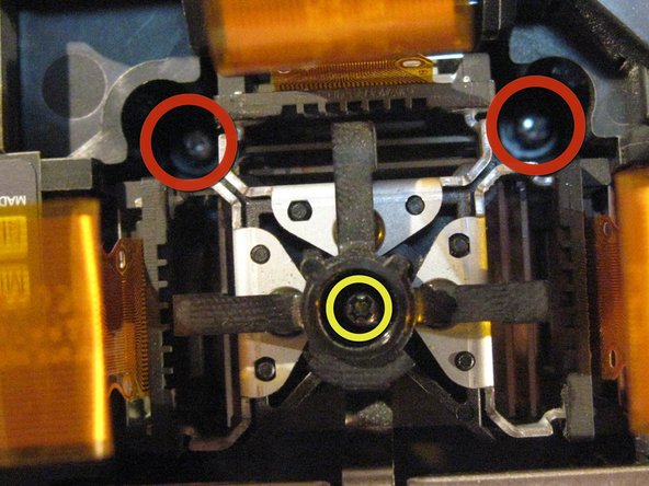
- To remove the LCD innards unscrew the two screws marked in RED circles
- DO NOT REMOVE the screw marked in yellow - this keeps the color lenses in place between the lcd's and the Prism (VERY IMPORTANT)
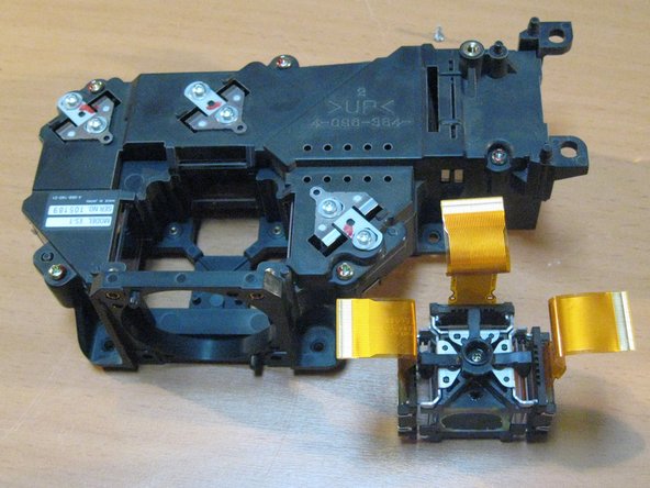
- Now, if needed you can remove the LCD assembly / Prism from the rest of the unit by simply pulling it out gently
- A shot of the LCD Assembly, Lens, Lamp and Mainboard.
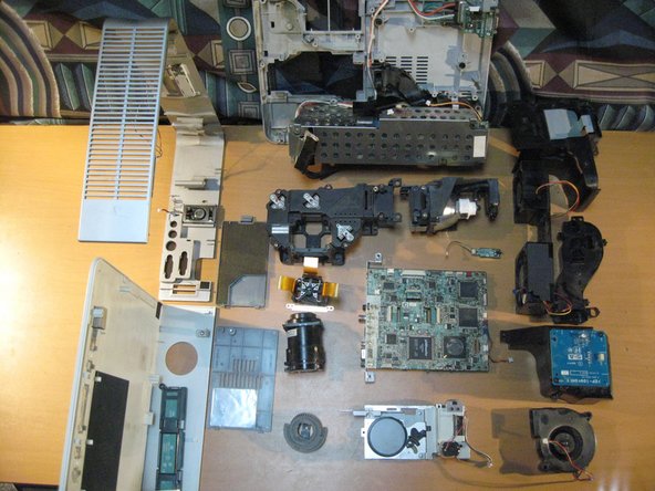
- Then a look at all of the Components. The Completed disassembly