Sony TR-63 Transistor Radio Teardown
ID: 1219
Description: This teardown comes with a bit of a history...
Steps:
- A bit more trivia...
- The huge success of the TR-63 helped Tokyo Tsushin Kogyo (aka "Totsuko") decide to change its company name to Sony Corporation in 1958. For the few years prior, "Sony" had simply been a brand name attached to the company's fledgling line of transistor radios. (Check out the retro Sony logo - I like it!)
- At the time, the company's co-founders felt the Japanese name was too hard to pronounce and remember by foreigners. They decided the name change would help them expand and become well known worldwide. And as they say, the rest is history.
- OK, enough babbling, let's get to work! This is the real Step 1...
- On the top of the radio you'll notice the earphone jack.
- Unscrew and remove the metal jack collar using a flathead screwdriver or other flat tool.
- Unscrew the large decorative screw in the center of the tuning dial by hand...
- ...and then you can remove the screw and lift off the tuning dial.
- Turn the radio over with its back facing you.
- It's safe to say the warranty on this radio long ago expired -- so we're going to fearlessly open it up in the following steps...
- In these photos, the gridlines on the green background are 1 cm square, so you can get an idea of the size of the radio.
- Carefully pry open the case from the bottom edge.
- Boy, this is a lot easier to open than an iPod! (Spudger not required.)
- On the inside of the back cover, you'll find the product label. Notice the official company name, Tokyo Tsushin Kyogo Ltd. I've seen photos of later versions of the TR-63 which say "Sony Corporation" there instead.
- I'm not sure what happened to the corner of the label - perhaps after all these years in the back of my closet it was likely eaten by a grue?
- Here's the circuit board inside, in all its glory.
- This radio takes a user replaceable battery! (Standard 9V transistor battery.)
- Using a Phillips #1 screwdriver, remove the lone screw in the center holding the circuit board in place
- Fortunately the Torx screw wasn't yet invented when they built this radio...
- Now gently lift out the circuit board.
- You may need to wiggle it a bit - you have to get the volume dial to clear its opening before the circuit board will come out of the case.
- Set the circuit board beside the case, being careful not to damage the thin wires going to the earphone jack and speaker.
- The earphone jack is composed of a few strips of metal. It also acts as a switch - when the earphone is inserted, contacts are opened to disconnect the built-in speaker.
- Carefully lift out the earphone jack assembly and set it aside from the case, still connected to the speaker.
- The speaker is fastened to the case with small clips held down by two nuts.
- Use a 5mm nutdriver to loosen the nuts.
- You may find the space a bit tight to fit a nutdriver in close to the case edge. If so, you can try using needlenose pliers instead to loosen the nuts.
- Once the nuts are loosened, you can separate the speaker from the case.
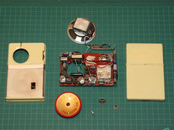
- Here's the circuit board, earphone jack and speaker after they've been removed from the case.
- Notice that there are components mounted on both sides of the circuit board. Perhaps the resistors and capacitors on the solder-side were a last minute design change?
- On the other hand, the circuit board is so tightly crammed on the component side there probably wasn't enough room for everything on one side.
- Here's a closeup of the solder-side of the circuit board.
- Unlike modern electronics, you can tell this radio was assembled and soldered by hand.
- I wonder what mark my old high school electronics teacher would have given to this work? :)
- Here's the component side of the circuit board.
- You can see the various components in these views of the circuit board. Remember, these are all discrete components here -- no integrated circuits! But state of the art at the time, a lot of circuitry crammed into a small space.
- Six of the gray components with an oval cross-section (marked or stamped with "Sony") are transistors.
- The 7th similar looking gray component is a varistor. It's the one at the front left of the circuit board in the 3rd photo in this series.
- Say, do they still teach the resistor colour code in schools these days? :)
- Here's a closeup of the volume dial / on-off switch
- An eccentric cam in the middle of the dial opens and closes a metal contact (marked with green square) to disconnect/connect the power to the circuits.
- A few more miscellaneous views of the components, while we're at it...
- The gray components with an oval cross-section are transistors.
- Finally, here are all the pieces of the fully disassembled TR-63 transistor radio, with both front and back views of the circuit board.
- That's it!
- This radio is just one of many Sony gadgets I would come to own over the years. I hope you enjoyed seeing it taken apart.