Mac mini Model A1176 CPU Replacement
ID: 1178
Description: Upgrade your mini's aging Core Duo processor to...
Steps:
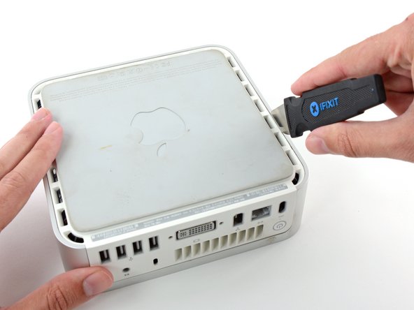
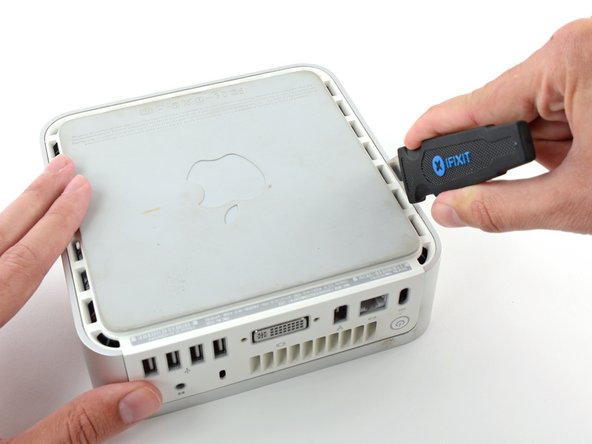
- Power down your Mac mini, disconnect all of the cables, and flip it over.
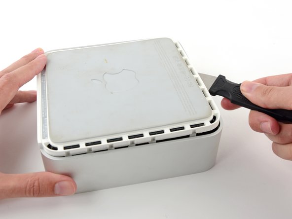
- Insert the Jimmy into the crack between the aluminum top housing and the plastic lower housing.
- The Jimmy should reach a stop about 3/8" down.
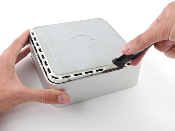
- Gently bend the Jimmy outwards to pry the crack open a little larger and lift the lower housing up a small amount.
- There are several plastic clips on the lower housing that fit into a channel in the aluminum top housing. Your goal is to use the Jimmy to push these clips inward enough to free them from the channel, while gently pulling up on the lower housing.
- Once you have the first side free, rotate the Mac mini and start prying up on the front edge.
- Use the same prying motion to both bend the clips inward and lift the lower housing up out of the top housing.
- You may need to move the Jimmy along the edge to pry up all of the clips. Be patient and do a little bit at a time.
- Keep working around the perimeter, freeing the clips along the final edge.
- Flip the Mac mini back over and lift the top housing off of the lower housing.
- Later in this guide you will remove several recessed Phillips screws. Bit drivers are generally too large to fit in the recesses, so be sure to have a thin shafted Phillips screwdriver on hand.
- First remove the AirPort antenna (the larger of the two), located near the power button.
- Slightly squeeze the two retaining arms toward each other and lift the AirPort antenna off its post.
- Squeezing the two posts excessively will surely break them off the internal frame. Work delicately.
- During reinstallation, you will have to slightly squeeze the two posts together so they fit into the openings on the AirPort antenna board.
- Use the tip of a spudger to slightly lift the left side of the ZIF cable lock up from its socket.
- The ZIF cable lock will lift about 1 mm and stop. Do not try to completely remove the ZIF cable lock.
- Lift the audio board ribbon cable up out of its socket.
- If it refuses to lift from its socket, the ZIF cable lock is not fully released. Make sure it is evenly lifted about 1 mm from the socket on the interconnect board.
- Rotate the mini so that the SuperDrive slot loading mechanism is facing you.
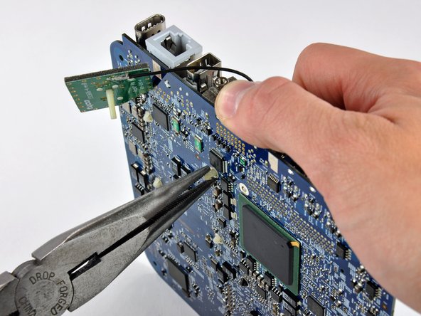
- Use a pair of tweezers to lift the hard drive thermal sensor cable connector up off its socket on the logic board.
- Use tweezers to grab the connector (as seen in the picture), not the wires.
- The connector is located under the optical drive opening, next to the PRAM battery.
- In the next few steps, you will remove the four Phillips screws securing the internal frame to the bottom case. Included in each step is an overview picture showing the general location and a closeup showing the actual screw.
- Remove the recessed Phillips screw near the power button securing the internal frame to the bottom housing.
- Remove the recessed Phillips screw near the sleep light securing the internal frame to the bottom housing.
- This screw is the longest of the four screws securing the internal frame to the bottom case.
- Remove the Phillips screw from the internal frame near the Bluetooth antenna.
- Remove the Phillips screw near the audio ports securing the internal frame to the bottom case.
- Gently lift the internal frame up from the bottom housing, minding the AirPort antenna and any other cables that may get caught.
- It may be necessary to pull up near the interconnect board to separate it from the logic board.
- Firmly grasp the power button cable connector with a pair of tweezers and lift it straight up off the logic board.
- Firmly grasp the sleep light cable connector with a pair of tweezers and lift it straight up off the logic board.
- Remove the single T10 torx lug securing the logic board to the bottom housing.
- Use the flat end of a spudger to slightly lift the logic board near the PRAM battery to separate it from the bottom housing.
- It will be necessary to gently pull the sleep light (shown in red) away from the mini to clear the edge of the logic board.
- Gently lift the free end of the logic board and wiggle the board as you pull it away from the I/O ports.
- Before removing the processor you must first remove the aluminum heat sink.
- To avoid bending the fins, don't squeeze the upper portion of the heat sink perpendicular to the length of the fins.
- A spring loaded plastic pin at each corner of the heat sink holds it firmly against the face of the processor.
- The pins have barbs at one end that expand once the pin passes through the logic board. The barbs must be squeezed together to fit through the holes in the logic board. Use extreme caution when squeezing the barbs together with pliers near the exposed face of the logic board.
- This step requires working with both hands and may be better accomplished with the logic board sitting in your lap.
- Using a plastic opening tool (or similar) in one hand, push down one pin holding the heat sink on the logic board. The spring under the pin will provide moderate resistance.
- While holding the pin down from the heat sink side of the board, use a pair of pliers in your other hand on the underside of the board to squeeze both barbs against the plastic shaft of the pin.
- With both barbs squeezed together, push the pin through its hole in the logic board.
- Repeat this process for each of the four pins holding the heat sink on the logic board.
- The heat sink is still attached to the logic board by the thermal sensor cables.
- Lift the heat sink off the processor and lay it on the AirPort card.
- Use the tip of a spudger to push the heat sink thermal sensor connector out of its socket.
- It may be necessary to work from alternating sides to 'walk' the connector out of its socket.
- Remove the heat sink and set it aside.
- To unlock the processor, use a small flathead screwdriver to rotate the processor lock 180 degrees counter-clockwise until the indicator is near the open lock symbol.
- Grab the processor by its edges and lift it straight up off its socket.
- Rotating the processor while lifting it out has the potential to break pins off inside the socket. Lift it straight up.
- Processors are extremely sensitive to electrostatic discharge. Only handle your processor by its edges.
- To aid in installation, processors and sockets have a small alignment arrow (shown in red) so the chip is installed in the correct orientation.
- Align the chip so that the arrow in its upper right corner corresponds to the arrow molded into the upper right corner of the socket.
- Carefully lower the processor onto its socket.
- Note that if you are upgrading from a core solo or core duo processor to a core 2 duo processor and wish to run operating systems of Lion or later, you must delete the hidden file /System/Library/CoreServices/PlatformSupport.plist after the upgrade.
- Use a small flathead screwdriver to rotate the processor lock 180 degrees clockwise until the indicator points toward the closed lock symbol.
- Now that the processor is in place, turn your attention to the heat sink.
- Apple uses a thermally conductive film that must be removed prior to reinstalling the heat sink.
- Use a razor blade (or anyother flat object such as a credit card, etc.) to remove all of the old solidified thermal material from the heat sink.
- Next use a small amount of rubbing alcohol to remove all traces of the old thermal material.
- Allow the heat sink to dry before proceeding.
- Apply a thin layer of thermal paste to the reflective silicon face of the processor.
- Check out our thermal paste guide for detailed instructions on applying thermal paste.
- Lay the heat sink on the AirPort card and use a spudger to reconnect the heat sink thermal sensor.
- Position the heat sink the same way it will permanently sit before lowering it onto the processor to avoid spreading thermal paste on regions not in contact with the processor.
- Gently lower the heat sink onto the processor.
- While holding the heat sink in place, press the four plastic posts down through the logic board to reattach the heat sink.